


The Scroll-Saw
Description
This section is from the book "Handy Man's Workshop And Laboratory", by A. Russell Bond. Also available from Amazon: Handy Man's Workshop And Laboratory.
The Scroll-Saw
The following description of a scroll-saw was given to the writer by a first-class mechanic, who assured him that it was one of the most useful articles he had in his shop; and judging by the number of times it was borrowed for cutting many shapes of ornamental woodwork, which can generally be found in almost any kind of house building, it spoke well for the mechanic and the efficiency of the saw. Brackets up to 3 inches in thickness were easily cut out, and all the ornamental scroll work on the outside of his beautiful frame house.
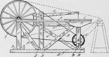
Fig. 38 - General side view of the scroll-saw.
A general side view of the saw is given in Fig, 38, while the lathe described in a foregoing article, page 27, is shown in dotted line- attached to the saw. The other illustrations, Figs. 39 to 44, give various details and sections. The reference letters, from A to Z, are duplicated on each figure, and tend rather to make an otherwise very simply constructed mechanism appear complicated.
While the proper sizes of lumber will be given, there is no reason why every part of the saw cannot be made from such material as may be found around almost any house.
It will be noticed that the framework consists of but three different sections of timber and 1-inch boards. The bottom framework is 2 feet 6 inches wide and 8 feet in length over all. The height from the floor to the top of the table, J, is 3 feet 7 1/2 inches. A list of material follows, with allowance for cutting where necessary:
Pieces. | In | In | Ft. | In. | |||
2............. | (A) | 3 | x | 4 | x | 8 | 0 |
2............. | (D) | 2 | x | 6 | x | 4 | 4 1/2 |
2........... | (C) | x | x | 6 | x | 3 | 4 1/2 |
2........... | (I) | 2 | x | 6 | x | 3 | 4 1/2 |
6..................... | (B) | 2 | x | 6 | x | 2 | 6 1/2 |
1......... | (P) | 2 | x | 6 | x | 1 | 0 |
1............ | (G) | 2 | x | 3 1/2 | x | 4 | 6 |
2............... | (H) | 2 | x | 3 1/2 | x | 4 | 6 |
1................. | (E) | 2 | x | 3 1/2 | x | 3 | 3 |
2...................... | (F) | 2 | x | 3 1/2 | x | 3 | 3 |
1................ | (Z) | 2 | x | 3 1/2 | x | 2 | 7 1/2 |
1................ | (Q) | 2 | x | 3 1/2 | x | 0 | 6 |
2......... | (U) | 2 | x | 2 | x | 1 | 0 |
1............ | (X) | 2 | x | 2 | x | 0 | 8 |
1............. | (J) | 1 | x | 36 | x | 3 | 0 |
2.................. | (K) | 1 | x | 9 | x | 2 | 9 |
1............. | (N) | 1 | x | 3 | x | 5 | 1 1/2 |
1............ | (M) | 1 | x | 3 | x | 4 | 10 1/2 |
1........... | (O) | 1 | x | 2 | x | 5 | 9 |
2............ | (L) | 1 | x | 2 | x | 2 | 0 |
2............... | (V) | 1 | x | 2 | x | 1 | 0 |
1............ | (W) | 1 | x | 2 | x | 0 | 7 1/2 |
1............ | (T) | 1 | x | 1 1/2 | x | 1 | 9 |
The upright D can be made from a 4 x 6-inch instead of two pieces as given in list, and the guides U with the block X can be made from 1-inch stuff.
When level, the saw frames M and N are 15 1/2 inches apart, out to out. Pieces are secured to the ends, 1-inch by 8-inch, cut to the same shape, and provided with holes for an adjusting bolt, with washers top and bottom. The holes should be of such a shape to give ample room for this bolt. Mortises are cut in D for the saw frame. 1 1/8 inches wide by 4 1/2 inches deep. They are centrally located with the frames, and the top edge of the first mortise is 3 inches from the top of upright D.
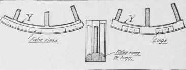
Fig. 39 - Extending the rim of the wheel.
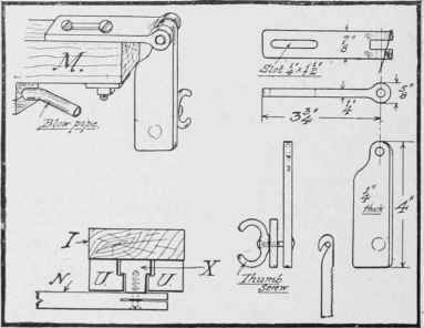
Fig. 40 - Details of the saw frame.
All the uprights and braces are cut where they come in contact with the bottom framework A and B; some of them being further secured to the inside face of the 3-inch by 4-inch sills with nails or screws. While nails will be permissible, if clinched, it will make a more satisfactory job to use screws throughout the construction. The bearings can be made of hard wood, if there is any difficulty in procuring suitable ones made of brass or iron.
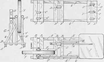
Fig. 41 - Plan view of the machine.
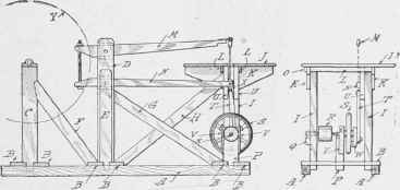
Fig. 42 - Vertical section of the machine.
An ordinary light buggy wheel, Y, is provided with 4 1/2-inch rim, made of 1/4-inch oak or pine, bent into shape by steaming or soaking in water, and secured to the tire of the wheel, Y, by means of two false rims, or lugs, as detailed in Fig. 39.
The saw blades are generally provided with a small hole at cither end. By means of an ordinary wood screw or a bolt, one end of the saw blade can be connected to the arm N and the block X. The arm M, however, has a different attachment, to allow for the necessary alignment of the saw blade, and in all probability this will necessitate the aid of a blacksmith, so a detail sketch is given (Fig. 40). The hole at this end of the saw blade is filed open to form a hook. Details of the guides U and the block X are also given in Fig. 40.
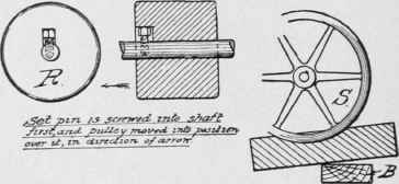
Fig. 43 - A simple foot-brake.
The balance wheel S was purchased from a junk dealer. It was found insufficient in weight, when heavy stuff was to be cut, SO an extra wheel was put on the end of the shaft beyond the out-bearing Q. A strip of wood W was secured to the vacant holes left by the spindle and crankpin of the old wheel, and a new center made for the end of the connecting rod T, giving a stroke of 3 1/2 inches to the saw. The two strips V, secured to the upright P, are used to hold down the bearing by means of a hardwood wedge driven over the top, as indicated in Figs. 41 and 42.
The hardwood pulley R is 6 inches diameter and 5 inches face. It i- secured to the shaft in the manner shown in Fig. 43. A simple brake, made from a piece of 3-inch by 4-inch timber, shaped on one edge to fit the rim of the wheel, and operated by the foot, is shown in Fig. 43, it having been omitted in the general views. The connecting rod T is made from hardwood, 21 inches long, 18 inches center to center of holes for two ordinary wood screws, to connect the ends to the block X and crank W.
Ordinary jig-saws are usually provided with bellows, so an arrangement similar in construction is given in Fig. 44. The bellows are of sheepskin or soft leather. The head is to be secured to the under side of the table J, and the bottom furnished with a leather flap valve on the inside. The opening must of course clear the arm N; so also must the tube connection.
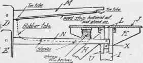
Fig. 44 - How the bellows is arranged.
The motive power of this scroll saw is of course someone at the crank end of the driving wheel Y, but there is no reason why the wheel and its supports should not be taken off, and a small gas or oil engine connected direct to the pulley R with a belt. When the saw is not in service the wheel may be taken off and the framework placed against the end wall, or even hung up.
Continue to:


My Books

