


The Elastic Pendulum
Description
This section is from the book "Handy Man's Workshop And Laboratory", by A. Russell Bond. Also available from Amazon: Handy Man's Workshop And Laboratory.
The Elastic Pendulum
By elastic pendulum is here meant a weight so suspended that more or less of the suspension is in the form of a spiral spring, so that the weight is capable of two movements in one plane - the usual pendulum vibration, and a vibration along the suspension. A very simple apparatus for readily and accurately finding centrifugal force may be constructed as shown in Fig. 174. As this is an experiment often given in laboratory courses, it is believed that a really accurate method will be welcomed. A small brass rod or tube about 125 centimeters long carries at the top a hollow adjustable weight, A. Below this a cylinder. B, of hard rubber, having two knife edges, C, and a yoke from which depend two spiral springs. Springs from cast-away shade rollers are excellent for this purpose. The springs support a weight, W, of about 700 grammes. As shown in the figure, the rod runs through the weight upon four grooved rollers E, mounted upon conical bearings. Above the weight is an adjustable collar, F. For convenience the vertical distance, C - G, is made 100 centimeters.
In use the apparatus is suspended from its knife edges, the spring is stretched by a weight of about 200 grammes and the collar F is set to hold the weight in the stretched position of the spring. Now take the vertical distance between the knife edges and the middle of the weight, and calculate the time of vibration of a simple pendulum whose length is this distance. Vibrate the apparatus through a small arc, and adjust the weight A until the time of vibration is that above calculated. No great care is demanded in this adjustment. A circular are of one meter radius, divided to thirds of a degree, is placed under the pendulum, so that G is at its zero point. Such an are can be very quickly made upon wood or cardboard with a rule, a pair of dividers, and a table of chords. Put a loop of thread around the weighl W, and pull it up the arc. It will be readily seen that upon releasing the weight at some particular point of the arc, the central acceleration at its fall will exactly balance the tension of the spring. This point can be found to a fraction of a degree after a few trials, and is indicated by a slight tick caused by the weight leaving the collar and returning against it. Call the angle so found 6, the distance through which the weight falls vertically S, and V its acquired velocity, we now have: S ==r versin θ and V2 = 2 g r versin θ
2 But the centrifugal force F = (WV2)/gr and therefore:
F = 2 W versin θ
The result is readily verified by adding weights to W until it just leaves the collar. Several trials have shown an agreement well within one per cent.
A weight swinging from the end of a spiral spring traces an interesting variety of curves, according to the ratio of the pendulum and vertical periods. The ratio may be varied by making more or less of the suspension of inelastic string, and varying the suspended weight. A ring is screwed into the ceiling of a high room, and through this ring a string is passed and to the hanging end of the string is attached the spring and weight. The weight is a brass tube about 10 centimeters long, having a bail at the top and a plug of lead at the bottom. The weight may be-added to by putting shot in the tube. A record of the curve traced by the moving weight is obtained by attaching a "pea" lamp to the lower end of the weight; supplying this with current from two very light wires coming in from one side, and photographing this light by a camera placed vertical to the plane in which the pendulum swings. A lamp may be selected giving practically a point source, and the small wires do not sensibly affect the motion of the pendulum.
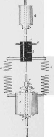
Fig. 174 - Details of the elastic pendulum.
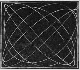
Fig. 175 - Curve obtained when weight is drawn aside and lifted - ratio 1/1.
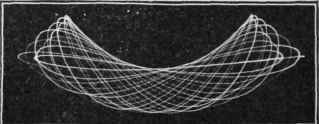
Fig. 176 - When weight is deflected and raised - ratio 1/2.
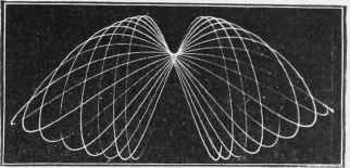
Fig. 177 - When deflected and depressed - ratio 1/2..
First case: When the ratio is 1/1. It was not found possible to exactly produce this ratio with springs of brass or steel; the vertical vibration being too fast when the whole suspension was spring. The best that could be done was a ratio of about 87 to 100, which is, however, near enough to enable us to see what the curve would be, were the exact ratio 1 to 1 obtainable.
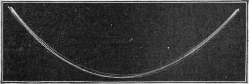
Fig. 178 - A limiting condition - ratio 1/2.
Fig. 175 shows the curve obtained when the weight is drawn aside, raised, and released. It is readily seen that the cycle would be complete after three revolutions to the right and three to the left, were the ratio exactly 1 to 1. When the weight is drawn aside and pulled down, exactly the same curve is described. There is, however, a limiting condition when the weight is just sufficiently lowered that the upward acceleration of the spring bal-ances the downward acceleration of gravity. We then get the curious case of a freely-moving pendulum whose bob deserihes a straight line.
Second case: Ratio 1/2. Fig. 176 shows the curve ohtained when the weight is deflected and raised; Fig. 177 when deflected and depressed. In Fig. 177 the cycle is incomplete. The horizontal component of motion dies out rapidly, and before the reverse half of the cycle is reached the pendulum has lost its directive force. In Fig. 176 it will he noticed that the contraction of the successive loops is due to falling off in amplitude of the pendulum.
Case two also presents a limiting condition shown in Fig. 178. Here the path is a parabola, and it is interesting to note that the upper loops of Fig. 177 are tangent to this parabola, when applied to it, and that it coincide- with the median line of Fig. 176.
When the ratios are made less simple, the curves become more complicated. Fig. 179 corresponds to a ratio of 2/3.
No attempt is here made to treat the matter analytically. These cases do, however, present new and interesting matter to the mathematician, should the present state of analysis he found equal to the problem. In general, we may remark that the shapes of the individual loops of the various curves are those of the corresponding aliquot ratios in simple harmonic motion, but the point of departure moves ahead with each successive loop.
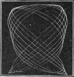
Fig. 179 - Curve made with a ratio of 2/3.
Continue to:


My Books

