Tongueing Planes
Description
This section is from the book "Woodwork Joints", by William Fairham. Also available from Amazon: Woodwork joints.
Tongueing Planes
Fig. 124 shows the end view of a tongueing plane for working matched joints out ofthe solid. The method of holding and using the plane is similar to the directions given for using the plough. The part lettered F (in front) represents the fence, which in this case is not adjustable.
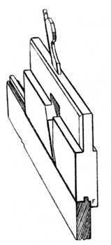
Fig. 124 .
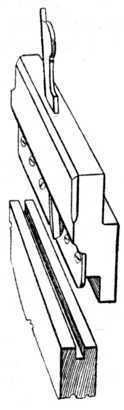
Fig. 125 .
End Views of Tongueing and Grooving Planes.
In description Fig. 125 is similar to Fig. 124 . The steel skate runs in the groove and supports the cutting blade similar to that in the plough plane, and provided a grooving plane of this type is of suitable width it may be used for making grooves for loose tongues. There is on the market a metal plane which is speciallydesigned with handles at both ends. This plane carries a grooving iron on one side and a tongueing iron on the other side; thus with one plane both the tongue and the groove can be worked.
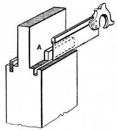 Fig. 126. - Tongueing Shoulders of Tenons.
Fig. 126 shows the method of tongueing the shoulders of tenons as used in thick timber which is to be veneered on the face. A temporary piece of wood (A) is put between the tenon cheek and the saw, thus forming a guide for the latter. After cutting one saw kerf a thicker piece is made and a second saw kerf cut; the waste between the saw kerfs is now removed with an 1⁄8 in. chisel and this completes the groove. A tongue of this type acts as an extra tenon and prevents the joint from "lipping" (becoming uneven) on the face side.
Continue to:
My Books

