Position
Description
This section is from the book "Text-Book Of Modern Carpentry", by Thomas William Silloway. Also available from Amazon: Text-book of Modern Carpentry.
Position
The strains to which the timbers of a structure are subjected will always be governed by their position; and their particular inclination will increase or diminish these strains in accordance with the laws of mechanical forces.
Plate II
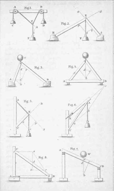
To the side of a beam, as shown at Fig. 1, Plate II., affix two pulleys, A and B. To the ends of a string passing over each, attach weights, as C and D. At some point of the string between the pulleys, as E, tie another; to the end of which affix weight F, which must be lighter than the sum of the weights C and D.
If the work be then left to itself, the point E will assume a certain position, and the whole will remain at rest; and, if the arrangement be disturbed by pulling down or lifting up either of the weights, each part will recover its original position when left free.
It is thereby proved, that, when in that position alone, the parts are in equilibrio. If the position of the strings, when the weights are thus balanced, be drawn on paper, and any portion of the line Ei be divided into a scale of parts representing the number of pounds in the weight F, the line AE be continued to h, and the line ih be drawn parallel to EB, then ih, measured'by the scale, would show the number of pounds weight at D; and the line Eh, measured in the same manner, the number of pounds in the weight C: or, in other words, the three sides of the triangle Ehi will be respectively proportionate to the three weights. Therefore, to ascertain to which weight either side corresponds, we have but to find which weight draws in the direction of that particular side.
As a deduction of the foregoing, we have the following rule: If a body be kept at rest by three forces, two of which are represented in magnitude and direction by two sides of a triangle, the third side will represent the magnitude and direction of the other force.
Strains On Timber. Pi.II
Smith. Knight & Tappan. EngTs..
Note. - Before proceeding to the immediate consideration of the strains to which timbers in a frame may be subjected, the student should make himself familiar with the mechanical principles demonstrated by Fig. 1, Plate II., as the principles therein contained are the base on which rests the science of carpentry.
We will now suppose that the point E, in Fig. 1, - instead of being sustained by the weights C and D, which act in the direction Ea and E6, as shown at Fig. 2, - is supported by timbers HE and JE. The weight F being suspended from the point E, the timber HE will sustain a force equal to that which is exerted in the direction of E6; and JE, a force equal to that exerted in the direction of Ea.
To determine these forces, we proceed as follows: Let any portion of the line EF, as Eo, represent the weight F. Draw op parallel to HE; and op, measured by the scale, will represent the weight sustained by HE, and oq that sustained by JE.
From the above data we deduce the following: 1st, A force or power applied to the end of a timber always acts in the direction of its length.
2d, If a post be somewhat inclined, as AC, Fig. 3, and another timber put against it, as BC, the post will be relieved of a part of the strain; for each piece will support a weight proportional to its own inclination.
3d, Should a weight be applied to the apex of two pieces of like inclination, as at Fig. 4, it will exert an equal strain on each.
1th, A weight, applied as shown in Figs. 3 and 4, tends to spread the timbers apart at the lower ends. In Fig. 3, we have supposed them to rest against an immovable abutment. It is obvious, that, the strain being a direct thrust, a tie connecting A and B will be an equivalent to the abutments. Fig. 4 represents this, AB being the tie-beam.
5th, If an inclined timber, as AB, Fig. 8, be cut at the ends so as to rest level on the walls, it will have no tendency to slide; and therefore, so long as it remains in this position, will not exert the slightest thrust on the walls.
Continue to:
My Books

