Chapter IV. Third Year Models (Wood). A Hanging Lamp Bracket (Fig. 1)
Description
This section is from the book "Handcraft In Wood And Metal", by John Hooper, Alfred J. Shirley. Also available from Amazon: Handcraft In Wood And Metal.
Chapter IV. Third Year Models (Wood). A Hanging Lamp Bracket (Fig. 1)
Object
A model designed chiefly to introduce shaping, cutting with bow saw, and working with spokeshave and file. Also as an exercise in simple recessing.
The Joints introduced are a simple mortise and tenon joint, and secret screwed fixing described below.
Decoration in the example illustrated is a simple outline vee tooled, one side of the cut having the sharp edge removed (see section on front elevation). The background can be coloured for effect, certain shades of blue, green, or red harmonizing well with oak.
The Process
1. Prepare: | English. | Metric. | |||||||
1 piece for Back | 14 | X | 6 | in. | 35 .5 | X | 15.25 | cm. | |
1 „ „ Shelf | 9 | X | 8 | in. | 23 | X | 20.5 | cm. | |
1 ,, ,, Bracket | 6 1/4 | X | 2 1/2 | in. | 16 | X | 6.5 | cm. | |
2. Plane up each piece to thickness, reduce back only to width.
3. Mark a centre line on back, freehand the curve on left side, duplicate right-hand side with tracing paper.
4. Plane one edge of shelf, set out shape with compasses.
5. Plane one edge of bracket, set out shape with compasses.
6. Gauge mortise on back (both sides) and tenon on bracket. Bore § in. hole and finish mortise with firmer chisel.
7. Slot screw the bracket on to the shelf (see later).
8. Fix back in bench vice, and saw curves (1/16. outside line) with bow saw. Repeat process with bracket and shelf.
9. Finish each piece with spokeshave, file, and glass-paper.
10. Draw design on back, and outline with vee tool.
11. With a small firmer chisel merge one line of the cut on to the background.
12. Clean up all surfaces, and screw the model together.
13. Paint in background of recessing.
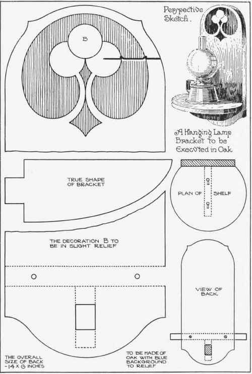
Fig. i.
Slot Screwing.
1. The bracket piece (A in diagram) should have two 3/4 in. x 6 in. screws driven in until a projection of 1/4 in. is obtained.
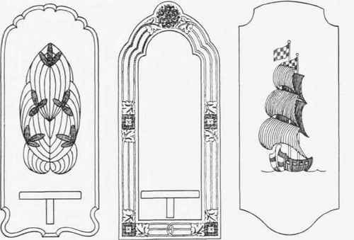
Fig. 2.-Alternate decorative treatments for back of lamp bracket-vee tooled, painted and inlaid.
2. The centre of these screws should be marked on the underside of shelf, then holes are bored exactly the size of the screw head 1/4 in. deep.

Fig. 3.
3. Slots are cut in the shelf (see plan in Fig. 1) coinciding with the thickness of the screw shaft. See B in diagram.
4. With a small firmer chisel bevel the inside of slot to coincide with the bevel of screw head underneath. The screw heads can then be entered in the bored holes, the bracket pressed down, and tapped along the grooves with a hammer, thus forming a secret screwed joint.
Continue to:
My Books

