


Wooden Bridges, Viaducts, Etc. Part 5
Description
This section is from the book "Elementary Principles Carpentry", by Thomas Tredgold. Also available from Amazon: Elementary Principles Of Carpentry.
Wooden Bridges, Viaducts, Etc. Part 5
341. The additional weight of the trains and other requirements of an increased traffic led to attempts at strengthening the earlier forms of the bridges used on railways. One of these resulted in the Improved Howe Truss, shown by Plate XLIV., which was used for a double line on the Philadelphia and Reading Railway. The clear span was 160 feet. The trusses were three in number and 23 feet deep. The upper strings were composed of four pieces, each 15 inches deep, and together 27 inches in width. The bottom strings also consisted of four pieces, each 20 inches deep by 27 inches total width, keyed and bolted together.
Plate XLIV.
BRIDGES.
IMPROVED HOWE TRUSS. Philadelphia, and Heading Railway.
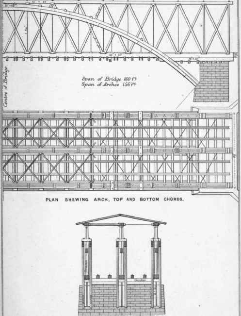
CROSS SECTION A. B

The sectional area of the upper strings of the three trusses was 1215 square inches, and that of the bottom strings 1620 square inches. The arches, in which for the most part consisted the improvement over the ordinary Howe truss, were six in number, one on each side of each truss, and were formed of the best pine, in pieces about 24 feet long by 4 1/4 inches wide and 15 inches deep. There were four such pieces in each arch, making together 8 1/2 inches wide by 3'0 inches deep, and giving a sectional area of 255 square inches. The pieces were made to break joint at every 6 feet. The sectional area of the arches collectively was 1530 square inches. The main braces were 8 inches by 10 inches, and the counter-braces 8 inches square. The width of each panel was about 10 feet 3 inches, and the vertical tie-rods were 1 5/8 inch diameter.
342. Plate XLV. shows another modification of the principle of constructing frame bridges, introduced by Mr. D. C. McCallum, known as the "Inflexible Arched Truss," and which is now more generally used than any of its prototypes. The upper string, instead of being horizontal, is arched, and the ties, instead of being vertical, radiate to the centre of the arched string. The bridge shown by Plate XLV. was designed for a single line, and had a span of 200 feet. The depth of the truss in the centre was 26 feet, and at the ends 21 feet. The arched top had two pieces of 7 inches by 11 inches, one piece 16 inches by 11 inches, and one piece 7 inches by 11 inches, together giving a sectional area of 407 square inches, or 814 square inches for both sides. The bottom string was composed of four pieces, each 7 inches by 14 inches, but which only afford an available clear sectional area, excluding notches and scarfs, of 234 square inches, or 468 square inches for both sides. The main braces, which projected 32 feet from the pier, were each 11 inches by 16 inches. The ties, of which there was a double row inserted between the chords, varied from 9 inches by 13 inches at the abutments to 9 inches by 6 inches at the centre. The counter-braces were 9 inches by 6 inches throughout.
Plate XLV.
BRID GES, Mc Callum's Principle .


343. Plate XLVI. shows a bridge of 150 feet span on the McCallum principle adapted for common roads. The following dimensions are given by the author of the paper from which the foregoing description of the McCallum bridge has been taken. Total length, 155 feet; clear width, 20 feet; depth of the truss at the centre, 20 feet 6 inches, and at the ends, 16 feet 6 inches. The arched top is composed of two pieces 7 inches by 10 inches, and of two pieces 6 inches by 8 inches, giving a sectional area of 236 square inches. In the bottom string there are two pieces 7 inches by 12 inches, making a sectional area of 168 square inches on each side. The braces are 8 inches by 10 inches at the abutments, and 6 inches by 10 inches at the centre.*
Plate XLVI.
BRIDGES,
Mc Callum 's Principle.


It is the practice in America to roof these bridges, and to cover in the sides with thin boarding, to protect them from the weather, by which means they may be made to last for about twenty years without renewal. Under ordinary circumstances, however, they seldom last for more than half that period.
344. The necessity for cheap railways in the thinly populated country of Norway, has led to the introduction, by Mr. Carl Pihl, engineer-in-chief to the Norwegian State Railways, of a system of timber-bridge construction, of which a description was given in ' Engineering' for July, 1867.
Fig. 110.

* Mosse's paper on " American Timber Bridges," in Min. Proc. Inst. C. E.,' 1802-3.
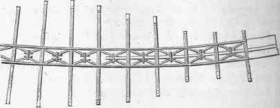
Figs. 110 and 111 show the principle on which these bridges were designed.
They were usually formed of round timbers, the greater number of which were of uniform length.
Fig. 111.
Each pier was formed of three sets of vertical timbers, assisted by raking struts which sloped inwards so as to meet at the head of the central vertical timber of the pier, as shown by Fig. 112.
The piers were crossed at intervals of 20 feet in their height by horizontal timbers, and from the points where the upper row of these cross the piers, diagonals proceeded upwards and inwards, and assisted in supporting the longitudinal timbers on which the rails were lala, directly in the centre of each span. The mode of connecting these diagonals with the longitudinal timbers is shown by Figs. 113 and 114.
The method of forming the junction of the vertical timbers of the piers and the horizontal timbers and diagonals, is shown by Figs. 115 and 116.
Fig. 112.
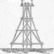
It will be seen that in the pier represented by Fig. 117, a second raking strut is shown on the left-hand side.
Fig. 113.

Fig. 114.

Fig. 115.

Fig. 116.

Fig. 117.

These additional struts were only applied on the outside of curved viaducts, straight viaducts having the struts arranged as shown in Fig. 112.
The span between the piers usually adopted for these bridges was 20 feet.*
* ' Engineering,' p. 5, vol. iv.
Continue to:


My Books

