


Section IX. Coffer-Dams, Shoring, And Strutting
Description
This section is from the book "Elementary Principles Carpentry", by Thomas Tredgold. Also available from Amazon: Elementary Principles Of Carpentry.
Section IX. Coffer-Dams, Shoring, And Strutting
Coffer-dams.
307. A coffer-dam is a watertight wall used to enclose the site of a work for the purpose of laying dry the foundation, as in the construction of sea-walls or the abutments and piers of bridges. Coffer-dams were used in the time of Julius Caesar, and were described by Vitruvius. Alberti, writing towards the close of the fifteenth century, gives a full description of a coffer-dam adapted for shallow water, and observes " that the foundations of piers should be made in autumn, when the water is lowest."*
A timber coffer-dam may consist of two or more rows of close piling, the space between the rows being filled in with well-punned clay, called "puddle."
308. The thickness of the dam, or distance between the outer and inner rows of piles, will depend on the depth of the water to be resisted, and to some extent on the stiffness of the soil through which the piles of the dam are to be driven.
The common rule for the thickness of a coffer-dam is to make it equal to the depth of water when such depth does not exceed 10 feet, and for greater depths to add to 10 feet one-third of the excess of depth above 10 feet.
When the height of the dam above the surface of the ground exceeds 12 or 18 feet, three and sometimes four or more parallel rows of piles are driven, thus dividing the
* ' Libri do Re aedificatoria,' First Edition, published in 1485 thickness of the dam into two or more equal divisions, each of 5 or 6 feet thick.*
The height at which the dam should stand above high water will depend on the situation; the more exposed it is, the higher will the dam be required; in ordinary cases 3 feet will be sufficient.
Before commencing a coffer-dam it is usual to dredge out all the loose soil on the site, which if allowed to remain would admit water under the puddle. The ground being thus prepared, piles of whole timber, called " guide piles," are driven at intervals of about 10 feet apart, to mark out the form of the dam; longitudinal timbers, formed of half baulks, called "walings," are then bolted on each side of the guide piles, one pair near the top, and another pair at about the level of low water. These serve the purpose of keeping in their places the intermediate piles, which may now be driven.
309. Fig. 92, which shows the form of the dam used by Telford for the lock at St. Katharine's Docks, is that mostly adopted in deep water. The piles A, A, A, were all of whole timber, each 12 inches square, and shod with iron weighing 15 lbs. The walings B, B, B, were in the first instance of half timbers, 12 x 6 inches, and were placed on both sides of each of the guide piles, but when the intermediate piles were all driven these were removed, and single walings of the same scantling were fixed on the two middle and inner rows of piles, and one waling 12 inches square on the outer row; the top walings of the inner row being double, as shown on Fig. 92.
The rows of piles were tied together with iron bolts, which passed through the piles and walings, and were secured with large nuts and washer plates.
All the piles used in a coffer-dam should be matched previous to their being driven, so that they may fit close
* Rankine, ' Engineering.' together, and prevent leakage through the joints as much as possible.
Fig. 92.
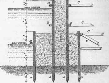
The length of the piles will depend on the nature of the soil and height of the dam. For a depth of water of 5 feet on a soft silty bottom, 25 feet in thickness, Mr. Hughes recommends that piles of 45 feet long should be driven 8 or 10 feet into the solid ground under the silt. For such a depth of water a double dam formed of three rows of piles would be required.
"When the depth of water in a tidal river is 10 feet at low water and 28 feet at high water, on a bottom of loose gravel and sand 12 feet thick, with clay underneath, the dam should have four rows of piles. The heads of those of the outer row should be driven down to within 1 foot of low-water mark and 5 feet into the clay, making a total length of 28 feet. The two middle and inner rows to be driven to the same depth into the clay, the former to stand 3 feet above high water, making a total length of 48 feet, and the latter about 11 feet above low-water mark, making the length, of the piles 38 feet.
A double row of waling-picces should be placed all round the tops of the piles, and be connected by wrought-iron bolts 1 1/4 inch square.*
Owing to the great pressure to which the sides are exposed in deep water, coffer-dams require to be strutted from the rear; this is usually effected by forming counterforts of piles at short intervals, according to the strength required. These piles should be tied together with walings and stiffened by struts, and the portion of the dam between the counterforts should be strengthened by horizontal struts from the ends of the counterforts. In dams enclosing a narrow space, as in those for the piers of bridges, the strutting might be effected from opposite sides, but they should be so arranged as to be easily removed and refixed, if required, as the work proceeds.
Struts in the body of the dam at a level much below high water are objectionable, as they would hinder the packing of the puddle and be a fruitful source of leakage afterwards, from the water creeping along them and causing the puddle to settle.
Iron bolts in the body of the dam, though also a source of leakage, are indispensable, in order to prevent the dam from bursting by the swelling of the puddle. These bolts should pass through the piles and be secured by nuts with iron plates, and large wood washers under both the heads and nuts, to prevent them working into the walings from the constant straining to which the dam is subject by the rise and fall of the tide.
In double dams these bolts are never allowed to go quite through from one side to the other, but if possible to break
* Harm and Hosking, 'Theory, Practice, and Architecture of Bridges.' joint, as it were, in the body of the dam. The bolts in the lower part of the dam (Fig. 92) are shown to go through the outer and middle rows of piles only.
Continue to:


My Books

