


Of The Points Of Fracture In A System Of Framing
Description
This section is from the book "Elementary Principles Carpentry", by Thomas Tredgold. Also available from Amazon: Elementary Principles Of Carpentry.
Of The Points Of Fracture In A System Of Framing
55. The balance of the parts in a system of framing is not so complicated a question as it is generally imagined to be; at least it is not so while our inquiries are confined to practical cases. A system of framing for spanning a wide opening is generally composed of two equal and symmetrical parts; and when it is loaded, the load is also similarly disposed. When the parts are loaded so as not to be in equilibrio, the system will divide itself into four parts only, and not more.
56. Again, if the system be balanced, and rupture be produced by a weight laid on at any particular point, the system may either divide itself into three or four parts. When the weight is laid upon the system at or near the middle of the span, it will divide itself into four parts. When the weight is laid upon it at some distance from the middle, the framing will generally divide itself into three parts.
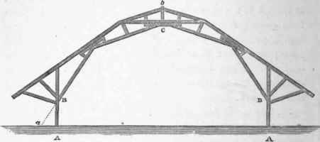
57. Let Fig. 33 represent a system of framing, which is similar to one applied by Mr. Seppings for the roof of a dock for building ships under cover.* The parts of this roof are obviously not in equilibrio, and the weight of the roof itself tends to cause fracture at the points B, C, and B', consequently to break the roof into four parts, A B, B C, C B', and BA'.
The uprights A B and A' B' have neither position nor weight to balance the spread of the superior parts; and the stability of the system depends wholly on the strength of the post to resist a cross strain, and the connection of the parts. By a proper disposal of the parts of this roof, the greater part of the strain arising from the weight of the roof itself might have been removed; and of course the roof would be much stronger to resist any other force, such as the wind, etc.; or it might have been constructed with less material and labour. This example has been cited to show that it is as essential that the principles of equilibrium should be known, as it is to understand the best method of stiffening and connecting the parts. The roof of Mr. Seppings is a fine example of the latter, and it has undoubtedly been for the purpose of leaving as much free space as possible that the upright posts only were used; for an oblique strut in the direction a B would have added much to the stability of the frame.
* The roof designed by Mr. Seppings is 95 1/3 feet span from A to A'; it is described in the ' Encyclopaedia Britannica,' art. Dock.
Fig. 33.
58. To find the position of the side posts so that the roof may be in equilibrio. Let G be the centre of gravity of that part of the frame between B and C (Fig. 34). Draw the vertical line bg through G, and from the middle of the depth of the framing at C draw the horizontal line C b, cutting the vertical line in b. Then draw the line A B 6, and A B is the position of the post.
Fig 34.

Here no notice is taken of the weight of the post itself, because it is too small to produce a sensible difference in the position.
59. In Fig. 33, B, C, and B', may be called the points of fracture, or the centres of motion, which in this case are easily found by inspecting the figure. In general it is more difficult to ascertain their position, and they are affected by so many circumstances, that it is not practicable to give a general rule for finding them.
But in most cases the positions of the centres of motion may be determined, with all the accuracy required in practice, by inspection; and it may be as well to illustrate this point before proceeding to examine these combinations further.
In the first place, suppose A C B (Fig. 35) to be a solid curved beam, resting on the abutments A and B. Let it be uniformly loaded and the strength equal in every part of its length, then the neutral line would be at the middle of the depth. Now if the curvature of the neutral line should not be the proper curve of equilibrium to the load, there would be a tendency to break at three points, one of which would be at C, the middle of the length. The other points would be near where the neutral line is most distant from the chord line A C and C B, but a little below, that is, at e and f in the figure.
Fig. 35.

60. If the beam should be much weaker at any point b than it is at e, the centre of motion would be in the point b, and one of the fractures would be there in the case of failure. But if the weak point were at d, the beam would be less liable to fail there, unless it should be very much weaker than at e.
61. Again, considering the strength to be equal throughout, and the load to increase from A and B towards C, then the fractures would take place at, or rather above the points e and f. On the contrary, if the load should increase from C towards A and B, the fractures would be below the points e and f.
Hence, by attending to the form, the strength of the parts, and the disposition of the load, in a system of framing, the centres of motion or places of fracture may be determined with all the accuracy that is necessary in practice.
62. But the constant load on a system of framing may be so balanced, that it will have no tendency to produce fracture; and the strength should be such, that any other load of a variable nature, as the weight of carriages, etc, upon a bridge, or the like, may also be supported. In order that the load may be thus balanced, the form of the supporting frame should be arranged, that the line or curve of equilibrium, which is in the direction of the resultant of the forces, may pass through or near the middle of the depth of every part.
When the nature of the load is known, the form of the curve of equilibrium may either be found by mathematical investigation, or by mechanical means.
Continue to:


My Books

