


Of Framed Floors. Girders. Part 2
Description
This section is from the book "Elementary Principles Carpentry", by Thomas Tredgold. Also available from Amazon: Elementary Principles Of Carpentry.
Of Framed Floors. Girders. Part 2
201. A method of strengthening a timber girder without increasing the depth is shown in Fig. 63, where a plate of wrought iron is bolted on each side of a timber beam, or as shown in Fig. 64, where a single plate or flitch of iron is placed between two planks or a beam cut down the middle and reversed.
Fig. 63.
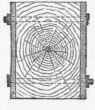
Fig. 64.
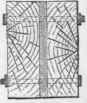
It might be questioned whether iron and wood thus combined would be effective, owing to the difference in the resisting powers of the two materials; but from the following experiments, which were made at the Royal Arsenal, Woolwich, in 1859, it would appear that there is some advantage as regards strength in a combination of this kind.
The beams were of fir, 18 1/2 feet long, resting on two supports placed 17 feet apart.
Exp. No. 1. - Two Memel Deals, each 9 in. x 3 in., laid side by side as in Fig. 65.
Fig. 65.
| Load. | Deflection. | Remarks. | |
At middle. | At 4 ft. 3 in. from middle. | |||
lbs. | in. | in. | ||
Load equally distributed over the length. | 2,310 | .510 | .375 | Broke in middle with 13,102 lbs. |
4,208 | 1.010 | .750 | ||
6,534 | 1.375 | 1.125 | ||
8,294 | 2.250 | 1.625 | ||
10,542 | 3.010 | 2.250 | ||
12,235 | 4.000 | 3.000 | ||
13,102 | 4.500 | ... | ||

Exp. No. 2. - Two Memel Deals, 9 in. x 3 in., placed as in
Exp. No. 1.
Load. | Deflection. | Remarks. | ||
At middle. | At 4 ft. 3 in. from middle. | |||
lbs. | in. | in. | ||
Load placed on middle of length. | 2,271 | 1.250 | .760 | Broke in middle with 6,800 lbs. |
4,597 | 2.500 | 1.750 | ||
6,166 | 3.500 | 2.750 | ||
6,800 | 4.500 | 3.000 | ||
Exp. No. 3. - Two Memel Deals, 9 in. x 3 in., as in No. 1, but bolted together as in Fig. 66 with twelve wrought-iron bolts, 3/4 in. diameter.
Fig. 66. | Load. | Deflection. | Remarks. | |
At middle. | At 4 ft. 3 in. from middle. | |||
lbs. | in. | in. | ||
Load equally distributed over the length. | 2,316 | .510 | .375 | Broke in middle with 13,503 lbs. |
4,204 | 1.000 | .750 | ||
6,466 | 1.625 | 1.250 | ||
8,186 | 2.010 | 1.625 | ||
10,441 | 2.750 | 2.010 | ||
12,116 | 3.250 | 2.500 | ||
13,503 | 4.000 | ... | ||

Exp. No. 4. - Two Memel Deals, 9 in. x 3 in. as last, but with a plate of wrought iron 9 in. deep x 1/2 in. thick placed between the deals, as Fig. 64, and bolted with eleven 3/4-in. bolts
Load. | Deflection. | Remarks. | ||
At middle. | At 4 ft. 3 in. from middle. | |||
lbs. | in. | in. | ||
Load equally distributed over the length. | 5,592 | .625 | .375 | Broke in middle with 34,862 lbs. |
9,293 | 1.000 | .750 | ||
14,692 | 1.500 | 1.125 | ||
16,617 | 1.750 | 1.375 | Both the timber and iron snapped asunder. | |
18,858 | 2.000 | 1.500 | ||
20,734 | 2.125 | 1.635 | ||
22,993 | 2.375 | 1.750 | ||
24,696 | 2.635 | 1.990 | ||
26,628 | 2.750 | 2.125 | ||
28,392 | 3.125 | 2.375 | ||
30,802 | 3.510 | 2.760 | ||
34,862 | 4.750 | 3.500 | ||
Exp. No. 5. - Two Memel Deals, 9 in. x 3 in., with wrought-iron plate 1/2 in. thick, as last.
Load. | Deflection. | Remarks. | ||
At middle. | At 4 ft. 3 in. from middle. | |||
lbs. | in | |||
Load on middle of length. | 4,759 | .740 | .490 | Broke in the middle with 18,079 lbs. |
7,148 | 1.000 | .740 | ||
10,148 | 1.500 | 1.000 | ||
13,372 | 2.333 | 1.500 | ||
16,491 | 3.500 | 2.500 | ||
18,079 | 4.500 | 3.broke. | ||
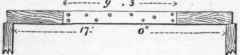
Exp. No. 6. - Beam as No. 4, but with the iron flitch only 9 ft. 3 in. long, or about half the length of the beam, as Fig. 67.
Fig. 67
Load. | Deflection. | Remarks. | ||
At middle. | At 4 ft. 3 in. from middle. | |||
lbs. | in. | in. | ||
Load equally distributed over the length. | 5,881 | .750 | .625 | Broke with 21,566 lbs. at the bolt. holes at one end of the iron flitch. The iron being uninjured. |
9,568 | 1.500 | 1.250 | ||
14,699 | 2.250 | 2.000 | ||
17,509 | 2.750 | 2.250 | ||
19,721 | 3.250 | 2.750 | ||
21,566 | Broke suddenly. | |||
Exp. No. 7. - Beam same as Last.
Load. | Deflection. | Remarks. | ||
At middle. | At 4 ft. 3 in. from middle. | |||
lbs. | in. | in. | ||
Load on middle of length. | 2,248 | .500 | .375 | Broke with 14,873 lbs. at one end of iron flitch, which was uninjured. |
4,459 | 1.000 | .625 | ||
6,715 | 1.500 | 1.250 | ||
9,012 | 2.000 | 1.500 | ||
11,273 | 2.750 | 2.000 | ||
13,413 | 3.500 | 2.750 | ||
14,873 | Broke. | |||
Exp. No. 8. - Rectangular Beam of Baltic Fir, 9 in. broad x 12 in. deep, in one piece, 18 ft. 6 in. long and 17 ft. between the supports.
Load. | Deflection. | Remarks. | ||
At middle. | At 4 ft. 3 in. from middle. | |||
lbs. | in. | in. | ||
Load equally distributed over the length. | 5,503 | .500 | .375 | Broke with 27,076 lbs. in two places near the middle, at a cluster of small knots. |
9,147 | 1.000 | .750 | ||
14,586 | 1.500 | 1.000 | ||
17,326 | 1.750 | 1.250 | ||
19,690 | 2.000 | 1.500 | ||
21,530 | 2.500 | 2.000 | ||
23,515 | 2.875 | 2.250 | ||
25,494 | 3.250 | 2.750 | ||
27,076 | 3.740 | 3.240 | ||
Exp. No. 9. - Rectangular Beam of Baltic Fir, in one piece, 6 in. broad x 9 in. deep, the length same as last.
Load. | Deflection. | Remarks. | ||
Amiddle. | At 4 ft. 3 in. from middle. | |||
lbs. | in. | in | Broke with 11,879 lbs. near the middle, at a cluster of small knots. | |
Load equally. distributed over the length. | 5,836 | 1 500 | 1.250 | |
8,645 | 2.625 | 2.000 | ||
10,619 | 3.500 | 2.500 | ||
11,879 | Broke. | |||
The following formula, taken from Hurst's 'Surveyors' Handbook,' will give the breaking weight of beams with iron flitches placed as in Figs. 63 and 64:
W = .D2/L (CB+30 t).
where B and D are the breadth and depth of the wood in inches, t the thickness of the iron flitch in inches, L the length between the supports in feet, and W the breaking weight at the middle in cwts.; C, a constant for the kind of timber as follows:
Values of C. | |
Teak........................................ | 4.006 |
English or Baltic Oak............. | 3.662 |
Canadian Oak......................... | 3.173 |
Baltic Fir................................ | 3.024 |
American Pine....................... | 2.774 |
Cedar..................................... | 2.219 |
The thickness of the iron flitch will depend upon the relative degrees of resistance of the iron and wood; in the rule it has been assumed at one-twelfth. The best proportion in each case requires, however, to be determined by experiment.
202. But it may happen that iron cannot be obtained except at considerable expense. It is therefore proper to show how it could be done without, particularly when we have the means of increasing the depth of the floor.
203. The principle of constructing deep girders is the same as that of building beams, and when properly done they may be made as strong as any truss of equal depth.
The most simple method consists in bolting two pieces together, with keys between, to prevent the parts sliding upon each other. The joints should be at or near the middle of the depth. Fig. 68 shows a beam put together in this manner. The thickness of all the keys added together should be somewhat greater than one-third more than the whole depth of the girder; and, if they are made of hard wood, as they ought to be, the breadth should be about twice the thickness.
Fig. 63.

204. Fig. 69 is another girder of the same construction, except that it is held together with hoops instead of bolts.
Fig. 69.

The girder being cut so as to be smaller towards the ends, will admit of these hoops being driven on till they are perfectly tight, and therefore make a very firm and simple connection.
205. In Fig. 70 the parts are tabled or indented together instead of being keyed, and a king bolt is added to tighten the joints; the upper part of the girder being in two pieces. The depth of all the indents added together should not bo less than two-thirds of the whole depth of the girder.*
Fig. 70.

206. Another method of constructing a girder consists in bending a piece into a curve, and securing it from springing back by bolts or straps. A girder constructed in this manner is shown by Fig. 71. Smeaton adopted a similar method of strengthening the beam of a steam-engine,† and the addi-
* A girder similar to this is described by Mathurin sousse, in his 'Art de la Charpenterie.'
† Rees's ' Cyclopaedia,' art. Steam-engine, plate i. Girders constructed in this manner have also been proposed by Rondelet, ' L'Art de Batir.' tional stiffness gained by bending beams in this manner is very considerable. The pieces should be well bolted, or strapped, to prevent any sliding of the parts. A beam of this kind might be built of any depth necessary in the erection of buildings, and by breaking the joints it might also be of any length that is likely to be required in the construction of floors.
The thickness of the bent pieces may be about one-fiftieth part of the bearing, and any number of them may be used to obtain the required depth, provided the whole depth of the curved pieces do not exceed half the depth of the girder; should they do so, straight pieces must be added to the under-side, so as to make the whole depth of the straight parts exceed that of the curved parts. When pieces cannot be obtained sufficiently long, care should be taken to have no joints near the middle of the length in the lower half of the girder.
Fig. 71 shows a girder for a 40-feet bearing, with the lower half scarfed at a, and a plain butt-joint in the curved part at b.
Fig. 71.

The rule for finding the scantling of these girders is to multiply 1 1/2 time the area of the floor supported, in feet, by the length of bearing of the girder in feet; the product divided by the square of the depth in inches will be the breadth of the girder in inches.
Continue to:


My Books

