


Observations On The Construction Of Bridges
Description
This section is from the book "Elementary Principles Carpentry", by Thomas Tredgold. Also available from Amazon: Elementary Principles Of Carpentry.
Observations On The Construction Of Bridges
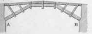
346. If A B (Fig. 1, Plate XLVII.) be a solid beam resting upon the supports A and B, so as to form one of the girders of a bridge, it will have to carry not only its own weight, but that of the planking and road material, and any heavy body moving over it. Now, in order to strengthen such a beam, without using a larger quantity of timber, we have only to make it deeper in the middle and shallower at the ends, as in Fig. 2, for a strain at C will have less effect in bending the beam than a similar strain in the middle (see Sects. I. and II.). But if the load be sufficient, however it may be distributed, it will cause the beam to bend; in which case the fibres at the upper.side d will be compressed, and those on the lower side e extended. A line may, however, be drawn at the middle of the depth acb, where the fibres remain in their natural state, being neither extended nor compressed. But all the fibres between c and d are compressed, and all those between c and e are extended; though not equally so, because the nearer a fibre is to the sides d or e, the more it is strained. As the intermediate part of the beam is very little strained, particularly near the middle of the length, the material in that part can be more effectually employed by placing it on the top and bottom of the beam, or by forming it into a truss, as Fig. 3, Plate XLVII., where the middle part about the neutral axis is omitted. On examining the forces exerted by the parts of this compound beam, it will be seen that the upper portion amdnb is wholly compressed in the direction of its length, and that the lower portion aresb is wholly extended in the same direction; and as timber offers the greatest resistance when strained in that direction, provided the joints are made secure, we have in this form an economical method of spanning an opening where the distance between the supports is not too great. It is also the elementary form of most of the roof trusses described in Section IV. Fig. 4, Plate XLVII., is an adaptation of the same principle which was used in the celebrated bridges of Schaffhausen, Zurich, Landsberg, and Wettingen. The continued tie A B prevents the compressed beams, which form part of the frame, from spreading; therefore this truss requires only to be supported, and has no other thrust on the abutments of the bridge than a solid beam would have. Framed bridges, such as that designed by Palladio (Fig. 102, page 242), may be referred to the same principle. By omitting the tie-beam in the last example, and making the abutments sufficiently strong to resist the thrust of the raking struts, we are led to the form shown by Fig. 5, Plate XLVII. But as long timbers require to be of a proportionate scantling, and cannot always be procured, it is desirable to construct the bridge with short pieces. Hence we are compelled to resort to such a combination as shown by Fig. 6, which is a very common form. It was adopted by Palladio in a bridge across the Brenta, and by Telford for one of 100 feet span over the Spey at Laggan Kirk (Plate XLI). Although a bridge on this principle might bear a constant load, it is not so well calculated to resist a variable one, which would soon derange it, because the strength of such a system must depend for the most part on the resistance offered by the joints, which cannot be made very strong
Plate XLVII
BRIDGE S.
Fig. 1.
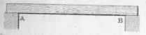
Fig. 2
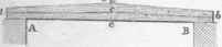
Fig.3.

Fig. 4.

Fig. 5.
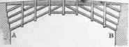
Fig. 6.
Continue to:


My Books

