


How To Measure The Strains In A Framed Truss
Description
This section is from the book "Elementary Principles Carpentry", by Thomas Tredgold. Also available from Amazon: Elementary Principles Of Carpentry.
How To Measure The Strains In A Framed Truss
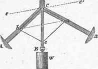
16. If, instead of placing the weight on the point where the beams meet, the beams were framed into a piece 'of timber, C E (Fig. 3), and the weight W suspended at E, the pressures would still be transmitted in the same manner, and would be found by the same means; C c representing the weight, C b the pressure in the direction of the beam C A, and C a the pressure in the direction of the beam C B.
In this case C E performs the office of the king post in a roof.
17. Hitherto the ends of the beams, marked A and B in Figs. 1 and 3, have been considered to be retained in their place by immovable supports; but they obviously have a tendency to spread; therefore they might be connected by a rope, a rod of iron, or another beam, which would answer a purpose nearly similar to the tie-beam of a roof. It is not quite the same, because a tie-beam has in general to support a ceiling, for which purpose a rope or rod of iron would not be sufficient.
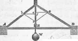
Let Fig. 4 represent an assemblage of this kind, where A B is the tie to prevent the lower ends of the beams A C and C B from spreading. This form is similar to the truss of a roof with a king post.
Fig. 3.
The strain on the tie A B may be found by drawing bf parallel to the tie A B; then, if C b represent the pounds or tons with which A C is pressed (found by Art. 14); bf, measured from the same scale, will be equal to the strain in the direction of the length of the beam or tie A B in pounds or tons. And the equal and opposite strain at B is measured by ea.
Fig. 4.
Again, in Fig. 5, which is a roof with queen posts, the pressure along the rafters A C and C B and tie-beam A B, arising from the weight of the roof, may be found in the same way as in a king-post truss. The strain on the strut H G may be found by drawing a vertical line H a to represent the vertical weight supported at H, and lines drawn from a parallel to the rafter and strut will represent the pressures in these directions respectively.
Fig. 5.

The horizontal line cb will represent the thrust on the straining sill G F, and the portion of the vertical line H a between H and c will represent the vertical pressure on the foot of the queen post D G or E F,
In a similar manner the stress on the straining-beam D E may be found, the vertical distance D d being set off equal to the portion of the weight of the roof supported at D plus the downward pull on the queen post D G, which is equal to the vertical pressure caused by the strut H G, and a portion of the load supported by the tie-beam, usually the floor of a garret, between G and F, and the ceiling of the rooms underneath.
Continue to:


My Books

