How Work Is Laid Out. Part 4
Description
This section is from the book "Carpentry for Boys", by J. S. Zerbe. Also available from Amazon: Carpentry for Boys.
How Work Is Laid Out. Part 4
Proper Terms
It is the application of the correct terms to things that lays the foundation for accurate thinking and proper expressions in describing work. A wise man once said that the basis of true science consists in correct definitions.
Picture Frames
In picture frames the mitered corners may have a saw kerf (C) cut across the corners, as shown in Fig. 44, and a thin blade of hard wood driven in, the whole being glued together.
Dovetail Joints
It is in the laying out of the more complicated dovetail joints that the highest skill is required, because exactness is of more importance in this work than in any other article in joinery. In order to do this work accurately follow out the examples given, and you will soon be able to make a beautiful dovetail corner, and do it quickly.
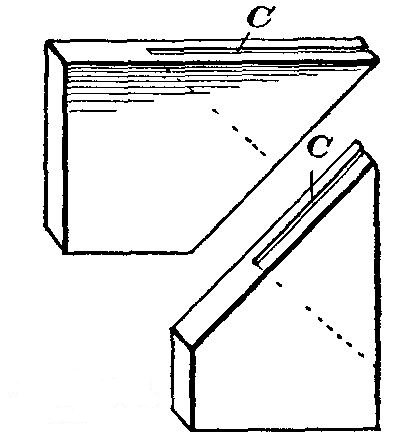 Fig. 44.
Preparing A Box Joint
In order to match a box joint for the inner end of a table drawer, the first step is to select two work sides. One work side will be the edge of the board, and the other the side surface of the board, and on those surfaces we will put crosses, as heretofore suggested.
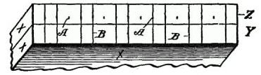 Fig. 45.
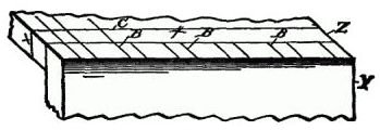 Fig. 46.
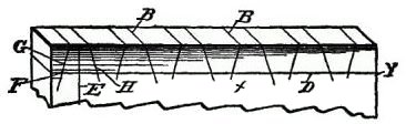 Fig. 47.
First Steps
Now lap together the inner surfaces of these boards (Y, Z), so the ends are toward you, as shown in Fig. 45. Then, after measuring the thickness of the boards to be joined (the thinnest, if they are of different thicknesses), set your compasses, or dividers, for ¼ inch, providing the boards are ½ inch thick, and, commencing at the work edge of the board, step off and point, as at A, the whole width of the board, and with a square make the two cross marks (B), using the two first compass points (A), then skipping one, using the next two, and so on.
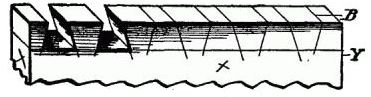 Fig. 48.
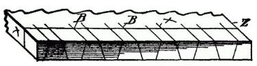 Fig. 49.
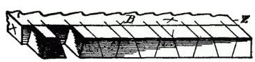 Fig. 50.
When this is done, turn up the board Z (Fig. 46), so that it is at right angles to the board Y, and so the outer surface of the board Z is flush with the end of the board X, and with a sharp knife point extend the lines B along with the grain of the wood on board Z,up to the cross mark C. This cross mark should have been previously made and is located as far from the end of the board Z as the thickness of the board Y.
We now have the marks for the outer surface of the board Z, and the end marks of board Y. For the purpose of getting the angles of the end of the board Z and the outer side of board Y, a cross line (D, Fig. 47) is drawn across the board X near the end, this line being as far from the end as the thickness of the board Z, and a vertical line (E) is drawn midway between the two first cross marks (A).
Now, with your compass, which, in the meantime, has not been changed, make a mark (F), and draw down the line (G), which will give you the working angle at which you may set the bevel gage. Then draw down an angle from each alternate cross line (A), and turn the bevel and draw down the lines (H). These lines should all be produced on the opposite side of the board, so as to assure accuracy, and to this end the edges of the board also should be scribed.
Continue to:
My Books

