Hot Water Circulation In Buildings Bath Boilers. Part 4
Description
This section is from the book "Plumbing Problems", by The Sanitary Engineer. Also available from Amazon: Plumbing Problems, or Questions, Answers and Descriptions Relating to House Drainage and Plumbing.
Hot Water Circulation In Buildings Bath Boilers. Part 4

Figure 90.

Figure 91.
Figure 93 shows the ordinary method of fitting up a hot-water boiler in Boston. A represents the range with its water-back. B is a copper circulating-boiler. They seldom have less than three couplings on the top, and from that to six. In the sketch four are shown. It is said that the object of the fourth or additional coupling is to obviate the frequent breaking of the lead pipes, which is caused by changes in the temperature of the water. It is also claimed that a coupling for each branch near the boiler is often cheaper. C is the tank from which the cold water is taken. The tank is filled through a ball-cock, which is on a pipe taken direct from the street-main. By this plan it will be seen that the pressure on the boiler is not excessive, and is a uniform one; the consequence is that the copper boilers prove durable. D is the cold-water supply to the boiler, from which branches should be taken to the cold-water faucets (except where drinking-water is drawn) and water-closet cisterns upstairs.
E is the hot-water pipe, while F is the return or circulation pipe, taken from the highest point of E. It will be seen that an expansion-pipe is carried up over and above the tank, with its end left open to permit the escape of steam. H is a cistern-valve, with an air-tube that extends above the water-line. It may be necessary to explain to some of my readers that without this the water would not flow down the pipe D when the valve is closed, and it serves the same purpose that the air-vent in a cask of liquor does. I is a valve-slide by which the valve H in the tank can be opened or shut. This is often placed on the outside of the tank, and sometimes in the bath-room or other accessible place down-stairs, so that it can be readily reached in case of an accident.

Figure 92.
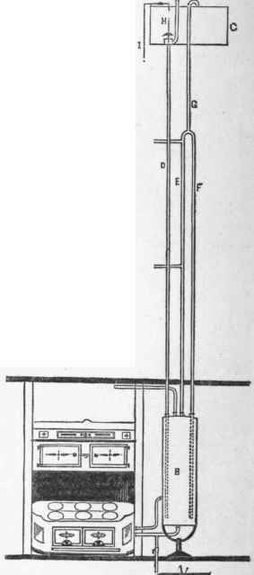
Figure 93.
These boilers are set on iron stands, just as in New York, but in old houses I have seen them placed on a soapstone slab with a brick foundation, on one side of which is an iron door. Inside of this latter is the sediment-cock to empty the boiler. It will be noticed that I have stated that fixtures upstairs should take the cold-water supply from the down pipe D, and not from the cold-water main to the tank K. In good work I believe this rule is observed, but in cheap work, or where plumbers desire to save every foot of pipe possible, they often take the branch from the rising main when that pipe is a little nearer to the fixtures to be served. Much of the complaint about ball-cocks jumping or making a noise, faucets leaking, and water-hammer, are due to this fact, and architects in writing specifications should be careful to specify from which pipe the branches should be taken, and then see that the specifications in that particular are carried out. Of course, I wish to be understood that the cold-water faucet over the kitchen-sink and the pantry-sink, or wherever it is desired to draw water for cooking or drinking, should not be supplied from a tank, but by a branch from the main in the cellar, independent of the pipe to the ball-cock at the tank, unless the disturbance of this ball-cock, whenever a faucet is suddenly shut, is no objection or annoyance.
In the issue of January 15, 1880, of the Sanitary Engineer an illustration of a double boiler was given. From correspondence concerning it at the time, it occurred to me that the explanations did not make entirely clear to all the readers of the paper the peculiar circumstances under which this form of boiler was used or required. For the information, therefore, of persons not residing in New York City, who may not fully understand it, I will explain that the class of dwellings in which double boilers are used are generally four stories high, besides the basement. The city water has not sufficient force to ascend above the second floor, and recently not always to that height. It is, of course, desirable to be able to draw hot water on every floor. This, however, would, under such conditions, be impossible, as the hot water cannot go above the cold water that supplies the boiler.
To place a tank in the attic or fourth floor from which the boiler is to be supplied, as shown in Figure 94, would involve pumping in that tank all the water that is afterward heated and used as hot water, as it would not flow there, as provided for in the sketch referred to. In the double-boiler system, therefore, the intention is to pump only the water required above where it will flow from the street-main, and this water is supplied to the inside boiler which furnishes the hot water for the upper stories.
It will be noticed that a double boiler, as shown in the annexed plan, consists of two copper cylinders, the space between the inner shell and the outer one being of the same capacity as the inside of the inner boiler - that is to say, an 80-gallon double-boiler means that the inside and outside boiler will hold forty gallons each. By reference to the drawing it will be seen that the cold-water supply passes under the sink, with a stop-cock at B, up alongside of the boiler, with a check-valve H, which is placed there to prevent drawing water from the outer boiler when the pump is working or the water is shut off in the street. Just above this check-valve a branch from this cold-water supply-pipe is taken and connected to the cold-water supply to the inside boiler which comes from the tank. On this is also placed a check-valve that will prevent the cold water from the tank from running to the main, while, on the other hand, it will permit the water from the street-main to fill the inside boiler at any time that the tank should become empty. It will be noticed that the hot-water pipes from both inside and outside boilers extend over and above the tank, with their ends open to permit the escape of steam. The hot water required at points above where the cold water will rise is taken from branches out of the hot-water pipe from the inside boiler, while the hot water required below that point is taken from the pipe that comes from the outside boiler. The tank is filled by a pump, which is usually placed in the cellar, instead of alongside the kitchen-sink, as shown in the sketch. A circulating-pipe is run from the outside boiler hot-water pipe, but not from the inside one.
It sometimes happens that these boilers are so fitted up that when the water from the inside boiler is drawn off it has collapsed from the pressure of the water surrounding it, by reason of some one ignorantly or carelessly emptying the inside one before the outside.
The arrangement of the sediment-cocks as shown in the drawing would prevent such an occurrence, because if the stop-cock G was opened, the water could not be drawn from the inside boiler until A was also opened, which would simultaneously empty the outer boiler. The outside boiler can be emptied without affecting the inner one, but not the reverse.
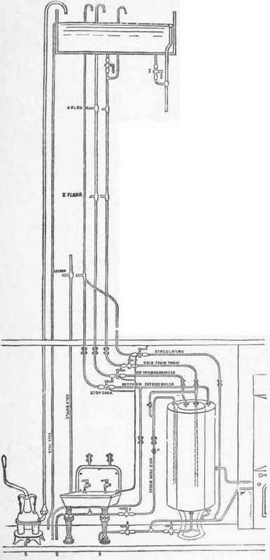
Figure 94.
Sectional Plan Of A Double Boiler, As Sometimes Kitted Up In First-Class Dwellings In New York City.
Continue to:
My Books

