


Remodeling An Elaborate Water System In A Hotel
Description
This section is from the book "American Plumbing Practice", by The Engineering Record. Also available from Amazon: Plumbing: A working manual of American plumbing practice.
Remodeling An Elaborate Water System In A Hotel
(Published In 1895.)
After the completion of the new Hotel Pfister in Milwaukee, Wis. it was found that the hot and cold water distribution and circulation systems were complicated, confused, and unsatisfactory, and Messrs. Halsey Brothers, of Milwaukee, were engaged to make such changes and reconstruction as were necessary to secure the efficient and positive operation and control of the system. Their examination disclosed an irregular arrangement and a great multiplication of pipes, many of them not properly connected , valved, or identified. Separate lines were not always distinguishable, and it was often impossible either to locate the pipes leading to certain fixtures or to command them afterwards without involving many others, thus making satisfactory maintenance and operation almost impossible. This state of affairs illustrates the necessity of installing large work by the simplest and most carefully developed direct system with experienced practical treatment of arrangement and connections as well as of adhering to the letter of specification and architects' general requirements on the plans. As it was impracticable to change the pipe lines already permanently built into the walls and floors and it was not permitted to disturb the decorations of the upper floors a series of careful measurements and plans was first made, locating and tracing every pipe line in the building down to the cellar where the engines, pumps, etc. were located. Then an accurate cellar plan was made to large scale showing the existing arrangement of pipes and connections, and on it a new system was laid out dividing the different lines into suitable groups, and arranging and connecting iron branches so as to conform as well as possible to the old arrangement and yet secure the utmost simplicity and directness for the new system and provide for its complete and easy control and maintenance.
REMODELING AN ELABORATE WATER SYSTEM IN A HOTEL.

Two distribution drums or headers were provided for the hot and cold water, and all the connections were gradually brought to them without interrupting the general service throughout the house, which was then occupied, and without shutting off any line except the one actually being connected at a given time.
Figure 1 shows the present arrangement of headers and distribution pipes. All the hot water is under tank pressure and is distributed from this point, but the cold water for cellar and basement is supplied from a separate 2-inch pipe under street pressure, from which branches are taken off and run on the cellar ceiling to the required points, where short risers are taken off and valved. The cold water header is supplied from the roof tank, but can be connected to the street pressure. The return circulation header is composed of 2 inch Y's and nipples. All valves have brass labels attached to them bearing the same number that is marked on the pipe lines that they control, and which is also recorded on a key provided with double references.
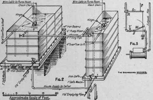
The cold-water supply is pumped into a 45,000-gallon pair of attic tanks built of riveted steel plates stiffened with heavy 4x4-inch angles around the sides and set on 4-inch rolled crossbeams that raise them above the bottom of 6-inch steel safe pans, which in turn are supported on heavy 15-inch girders across the top of brick walls. A large, heavy float made from a whisky keg is hinged by a 4-foot arm to the top of each tank, and its motion is limited by a check chain. A ¼ inch copper-wire cable is attached to the float and carried over pulleys to the pump-room, where the other end is secured to a lever L, Fig. 3, which is connected with another lever M that is loaded with a counterweight W, of 20 pounds, about half the weight of the float keg. When the water rises in the tank the ascent of the float keg slacks off its cable C and allows the counterweight W to pull down both levers. Lever M being attached to the stem of the steam valve, closes it and stops the pumps. As the water falls in the tank the operation is reversed, the descending float keg pulls back the cable raising the lighter counterweight and lifts lever M, opening the steam valve and starting the pump, and so on, automatically. Of course the automatic steam valve S can be fastened open, and the pump controlled at will by the hand valve V. Adjustments are made by attaching the cable to different points on line L. There are two pumps and two float cables, all similarly connected up to a shaft R, so that either float will control both pumps. There is also a gauge board in the pump-room with an index indicating the water level in the tanks.
Continue to:


My Books

