The Return To Automatic Valves
Description
This section is from the "Blast Furnace Construction In America" book, by J. E. Johnson, Jr.. Also see Amazon: Blast Furnace Construction In America.
The Return To Automatic Valves
The last two or three years have seen a development in this field which brings us back almost to the starting point. The gas-driven engine has received a great development in Germany and as the speeds at which it has to run in order to be successful are considerably higher than those customary with steam engines, the question of air valves has been one of great moment to the German engineers, and they have developed a system which modern workmanship and modern metallurgy have made possible. The design used by the American licensees of the Rogler patents, the Ingersoll Rand Co., is shown by Figs. 84, 85, 86, 87. The latter shows an 84 x 60 blowing cylinder head, equipped with these valves.
Each valve consists of three or more concentric rings held together by radial bars or bridges, the whole being stamped from a single thin plate of special steel.
The valve seat consists of similar but alternately spaced concentric rings, the openings between which constitute the ports and are covered by the valve rings when closed. Four small helical springs in the cover plate serve to seat the valve.
Fig. 82. Southwark air cylinder head, inside view.
The valve is extremely light in weight and requires but a slight lift to give full opening and its inertia is, therefore, very small.
For this reason the small tension of the springs is sufficient to seat the valve at the proper time without adding appreciably to the air resistance in passing through it.
Fig. 83. Southwark air cylinder bead, outside view.
The principle of this valve is not essentially different from that of the poppet valve of fifty years ago, but the details of the design are such as to constitute the difference between failure and success under modern conditions.
An American design of similar valves has been brought out by the Mesta Machine Company, of Pittsburgh, under the name of the Iverson Valve. These are shown in Figs. 88, 89, and 90. In this case the valve is independent of the spring, which is a flat spiral (not helical), spring, clipped to the back of the valve proper.
Fig. 84. Cross-section of Ingersoll Rogler Valve with seat, cap and springs.
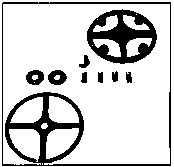
Fig. 85. Ingersoll Rogler Valve seat, cap, and springs disassembled.
The results with these valves in regard to providing the area necessary for inlet and discharge with minimum suction on the bottom of the indicator card, and minimum excess pressure on its top line, are claimed to be equal, if not superior, to the best of the mechanically operated valves. The clearance is small and the operation of the valves is noiseless.
Fig. 86. Top and Bottom views of Ingersoll Rogler valve complete.
These valves have one advantage also which I should hardly have believed if I had not seen the results myself. In vertical engines the inertia of the eccentric rods, rock-shafts, and other mechanism for actuating the air valves is sufficient to cause some vibration in almost all engines, and in those of the steeple type this has in many cases been excessive. In cases where these small automatic valves have been substituted for mechanically operated valves, the entire absence of any moving parts except these light valves themselves, which only move a fraction of an inch, eliminates this vibration.
Fig. 87. Blowing cylinder heads equipped with Ingersoll Rogler Valves inside and outside views.
I have seen engines running side by side, one vibrating almost dangerously and the other perfectly still. The manager who was then trying the valves out told me that the engine with the automatic valves had vibrated as violently as the other when it was positively operated.
Pig. 88. Valve plate and spring of "Mesta" (Iverson patent) automatic plate valve.
Fig. 89. Valve seat of "Mesta" (Iverson patent) automatic plate valve.
It is probably too early in this new development to say what its ultimate results will be, but if the promise of the present is fulfilled we shall probably witness, in the next few years, the elimination of much complicated and expensive mechanism from our blowing engines.
Continue to:
My Books

