The Baker Top
Description
This section is from the "Blast Furnace Construction In America" book, by J. E. Johnson, Jr.. Also see Amazon: Blast Furnace Construction In America.
The Baker Top
This may be considered as a modification of the Brown top in that it distributes the material in heaps on the main bell. It is shown by Fig. 42. Endeavor has been made in the design of this top to overcome the mechanical difficulties due to the great weight of the rotating parts, the large radius of the sliding surfaces in the Brown and the somewhat complicated mechanism required to drive it, and also to reduce to a minimum the height from which the coke is dropped so as to reduce coke breakage. The main bell, hopper, and lip ring are clearly shown by the drawing, and are of standard construction, but, as is necessary in most central types of stock distribution, the main bell is not supported on a single central rod; instead it is hung to the center of a horizontal equalizing beam from the two ends of which rods run up to the ends of the double main bell beam. A section of the equalizing beam, with its sharp-edged top to divide the current of stock, and prevent any disturbing action on the descent of the latter, is plainly shown on the drawing. The main bell rod on the far side is shown broken away below the top of the upper hopper, but a short piece is shown attached to the end of the main bell beam.
In this design there is a gas-seal bell practically identical with the upper bell of the ordinary non-rotating double-bell charging apparatus, but in this case the bell has fastened to it a plate which is elliptical in outline and is set parallel to one side of the conical surface, and constitutes a sort of slanting piston working in the receiving hopper, which is nearly cylindrical, flaring slightly at the top, as shown in the drawing. The upper bell is rigidly keyed to the lower end of its (central) bell rod. By means of this rod the bell with its extension plate Attached is rotated through a certain angle each time it is raised and lowered. When the upper bell is open, and in the position shown, the plate acts practically as a continuation of the lip of the receiving hopper and discharges the entire skip load on the opposite side of the furnace. The upper bell is then closed and opened again, which brings the deflecting plate into a position in the horizontal plane approximately to right angles of that shown. This delivers the next skip load on to the bell practically at right angles to the first one, the third is approximately opposite to the first, and the fourth practically completes the cycle, but if the "hunting tooth" effect used by Brown is desired, the completion of the cycle does not bring the deflecting plate back exactly to its initial position.
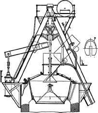
Fig. 42. Baker rotating top.
Instead of an arrangement of gears for rotation, recourse is had to what is known as the rifle-bar cylinder. This device has been in use for many years for rotating the bits of rock drills. The cylinder which operates the upper bell is immediately over it, and inverted so that it operates directly without the intervention of levers or other devices, which makes an extremely simple design.
The operation of the rifle-bar cylinder is shown by Fig. 43. The piston carries two helical vanes A which work in corresponding grooves or threads in the nut B which has ratchet teeth cut in its upper surface. These are engaged by vertical gravity pawls D in pockets spaced around the cylinder. They prevent the rotation in one direction of the nut B. A square opening at the top of the chamber on which the helical vanes are cast is an easy sliding fit on the square rod E, which carries on its top a circular plate F, to which it is rigidly keyed, and which has on its top surface ratchet teeth engaging with pawls G exactly the same as those of B and operating in the same direction.
On the down stroke of the piston, the action of the vanes forces either F to turn to the right or B to the left, but the ratchets G do not allow F to turn to right while the ratchets D do allow B to turn to the left, which it accordingly does. On the up stroke the pawls engage with the ratchet teeth C and prevent the backward rotation of B which thus compels the rotation of the disk F in its turn.
Thus every cycle (up and down stroke) of the movement of the piston forces the bell and deflecting plate to rotate through a given angle. The amount of the rotation is determined by the pitch of the helical vanes, and the stroke of the cylinder. The latter is intended to be constant and therefore the angle of rotation of the upper bell with its deflecting plate is also constant.
The upper portion of this cylinder has no function except to enclose the apparatus and prevent the entrance of the grit and dirt which always abound on top of furnaces, and which have done so much to destroy charging mechanisms. The cylinder is virtually a single-acting one, since the weight of all the parts acts downward and suffices for the down stroke, steam being used only for the up stroke and to cushion the down stroke.
This type of top has given good satisfaction at a number of plants, but its use has been abandoned at a number of others, since it was claimed that the benefit obtained from its form of distribution was not sufficient to offset the possibility of the small bell being stuck with its deflecting plate in one position, and dumping the stock to one point on the main bell continuously for a number of charges, or even hours, if this condition was not discovered. For it is evident that if the small bell fails to operate between skip loads the position of the deflecting plate will be left unchanged, while there is nothing to prevent the indefinite continuance of dumping in this position. This, of course, would make the worst possible type of stock distribution, and would ruin the work of any furnace in a very few hours.

Fig. 43. Rotating gear of Baker top.
There is with this design the possibility of jamming the deflecting plate against the wall of its slightly tapering receiving hopper by the entrance of lump material back of the plate, and while the probability seems slight, this chance, in addition to the discarding of the top by at least one large plant, has proven sufficient to reduce its popularity. It is probable for reasons which will appear later that the top has been successful at plants using lump ore, or a mixture of lump and fine, and less successful at plants using all fine ore. This is in accordance with the facts in regard to the use of these tops. Those within my knowledge at plants where the ore mixture is lumpy have given far greater satisfaction than those in the Lake Ore district.
Continue to:
My Books

