General Principle Of Group Respiration Apparatus
Description
This section is from the book "Human Vitality And Efficiency Under Prolonged Restricted Diet", by Francis G.BENEDICT, Walter R. Miles, Paul Roth, And H. Monmouth Smith. Also available from Amazon: Human Vitality and Efficiency Under Prolonged Restricted Diet.
General Principle Of Group Respiration Apparatus
The respiration chamber is of air-tight construction and supplied with a current of outdoor air by means of a rotary air-impeller. At a diametrically opposite corner of the chamber from this air-impeller is a pipe which conducts the air to a second rotary air-impeller of the same type and size. By means of a simple system of butterfly valves the absolute amount of air passing through the chamber can be adjusted at will. The air leaving the chamber is aliquoted by a method developed for this apparatus. A large portion of air is discharged freely into the laboratory room and two smaller portions, alike in amount, are discharged under special conditions into containers from which the air is withdrawn as desired. The air sample may be analyzed by volumetric analysis or, as is actually done in this case, the carbon dioxide may be removed by passing the air through soda lime.
Respiration Chamber
Personal visits to Stockholm and Helsingfors and inspection of both the Scandinavian chambers led to material modification in the design for the chamber built in the Nutrition Laboratory. Thus it was seen that the height could easily be reduced. Second, the entrance to the chamber was best made from the top; fortunately the unusually high ceiling of the calorimeter laboratory made this change possible without difficulty. The calorimeter laboratory is provided with excellent automatic heating and cooling arrangements for maintaining uniform temperature. Hence no special appliances for heating the new respiration chamber were needed. As a matter of fact, it was found subsequently that cooling rather than heating was absolutely essential.
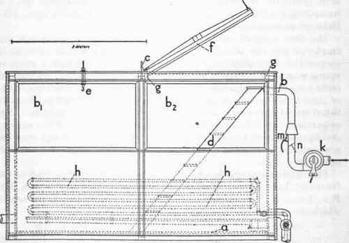
Fig. 6. - View of east end of group respiration chamber.
a, Inner wooden floor; b1 and b2, windows; c, suspension-rod supporting roof of chamber; d, step-ladder; e, hook for supporting ladder d when not in use; f, trap-door resting in groove gg when closed; hh, brine coil; k, rotary air impeller; b, opening into chamber for ingoing air; m, Bun-sen burner for heating ingoing air; n, butterfly valve.
The details of construction of the respiration chamber are given in figures 6 and 7. Figure 6 shows the window (east) end of the chamber. A cross-section of the chamber in the longest dimension from west to east is represented in figure 7.
The respiration chamber has an inner lining of sheet metal, which is absolutely air-tight. As this inner lining required a substantial wooden backing to prevent unnecessary wear or play by the buckling of the sheet metal, a framework was built on the floor of the calorimeter room from timber 4 inches square; this framework had a width of approximately 13 feet 3 1/2 inches and a length of 17 feet 9 1/2 inches. To this base were fastened the several uprights which were covered with a sheathing of 3/4-inch matched lumber. The framework on the floor was then lined with galvanized iron, which extended up 10 inches on the wooden walls of the chamber, for it was believed that the greatest stress and wear would be borne by these parts. The rest of the inner metal lining was made from tinned sheet iron. The inner metal lining of the chamber has therefore a length of 17 feet, a width of 12 1/2 feet, and a height of 7 1/2 feet. The outside of the chamber was finished with 1/8-inch "compo board," which was painted. Between the compo board and the inner wooden wall is an air-space of 4 inches.
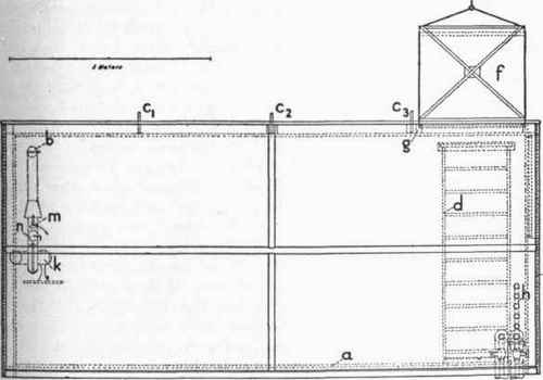
Fig. 7. - Cross-section of group respiration chamber from west to east.
o, Inner wooden floor; b, opening for ingoing air; c1, c2, and c3, 3/4-inch suspension-rods; d, step-ladder; f, trap-door; g, water-seal trough; h, brine coils; k, rotary air-impeller; m, Bunsen burner for heating ingoing air; n, butterfly valve.
To prevent excessive wear of the galvanized iron floor, it was necessary to install an inner wooden floor (a in figs. 6 and 7), which was made of 7/8-inch maple flooring, resting upon 2 by 4 inch wooden stringers, laid on edge. This floor was substantially made and well smoothed to secure a rigid base upon which groups of individuals could walk with freedom or perform severe muscular exercise. The original intention was to have the floor as nearly as possible air-tight, so as to consider as the flexible or movable portion of air inside the chamber only that above the floor. For this purpose a copper flashing was soldered to the bottom of the metal wall, turned in over the top of the maple flooring, securely tacked to the floor and filled in with shellac.
Although thoroughly seasoned maple was used for the floor, .in a very short time there was sufficient shrinkage to cause extensive diffusion of air through the slight openings. It thus became necessary to include the air in the space under the floor in the total' air volume of the chamber. A series of 1-inch holes were bored along the north and south edges of the floor near the walls, to facilitate free passage of air.
In the east end of the chamber are two large sheets of plate glass, 5 feet 10 inches by 39 inches (b1 and b2, fig. 6), set into rigid frames which terminate in the sheet metal interior wall. Both sheets of glass are well imbedded in a large amount of physicist's wax, which is then covered with shellac. These windows provide full illumination for the chamber, as there is but a 2-foot passage between them and the large double window on the outside wall of the calorimeter laboratory. Consequently it has never been necessary to use artificial illumination.
The roof of the chamber is suspended by three 3/4-inch iron rods (c1, c2, c3, fig. 7) attached to the structural steel beams in the ceiling of the calorimeter room laboratory. This construction is so rigid that a dozen men can walk at any place on the roof of the chamber without causing a perceptible sag.
The entrance to the chamber is in the northeast corner of the roof. A stout step-ladder, d, one end of which is attached to the wail permanently, leads down into the chamber. When desired, this ladder can be hooked up out of the way (see e), a counterpoise rope assisting in its elevation. The corners of the trap door, /, are made of strong sheet copper, reenforced with a wooden framework. This door is likewise counterpoised by a window-weight and cord running over two pulleys. When the door is lowered, the edge (which is 3 1/4 inches deep) fits into a trough, g, surrounding the opening into the chamber. This trough is approximately one-half to two-thirds filled with water, thus supplying a complete seal and perfect freedom in opening and closing.
In the east end of the respiration chamber is a brine coil, h, connected with the refrigerating brine service of the Harvard Medical School power-house. By opening the valves an unlimited amount of cold brine may be passed through this coil, and the heat generated by the subjects inside the chamber brought away rapidly. To hasten or facilitate this withdrawal of heat the electric fan, which is always placed inside the chamber to insure uniform mixture of air, may be so turned as to deflect the air against the brine pipes. The temperature of the room can be easily controlled by this method.
The special features to be emphasized in connection with this respiration chamber are: (1) it is absolutely air-tight; (2) it provides an airtight and easily opened and closed entrance by means of a trap-door and water-seal; (3) the glass windows at one end provide complete illumination; (4) provision for cooling is made with the brine coil.
As may be seen, the respiration chamber has relatively few new features. Indeed, any type of air-tight chamber providing entrance may be employed, but this,particular type of construction seemed to us best suited for the special purpose of the Nutrition Laboratory. As will be shown later, the shape and size of the chamber play a relatively small role. The entrance may be changed to one end of the chamber, if desired; and for experiments with large wild or domestic animate, such a change in location would be practically necessary. Heat may be brought away without using a brine coil if the chamber is perfectly airtight and some adequate system of cooling is used, such as exposing the metal walls to the free circulation of indoor air, rather than, as here shown, protecting them by sheathing, dead-air space, and finally compo board. The essentially novel feature of the whole installation is the maintenance, aliquoting, and analyzing of the ventilating air-circuit.
Continue to:
My Books

