


Wave Length In Wireless Telegraphy
Description
This section is from the book "Amateur Work Magazine Vol4". Also available from Amazon: Amateur Work.
Wave Length In Wireless Telegraphy
Oscar N. Dame
Since it has been determined that the velocity of all etheral waves is the same, practically, it may be noted that the length of each wave varies inversely with the frequency.
To explain this more acceptably to the average reader let us consider a rod of steel held in a vise at one end and strike a sharp blow. The rod will vibrate at a frequency depending upon the length of the rod. The frequency of vibrations under varying length of rod is noted by the higher or lower pitch of sound.
In the case of the vibrating rod, the period of vibration will be the same at all parts of the rod, and the amplitude will vary from nothing at the fixed end to a maximum at the free end.
Similarly, if a wire having one end insulated while the other end is held at a constant potential by earthing the end, be struck an electrical blow, electrical oscillations will be set up in the wire, the frequency of which will depend entirely on the length of that wire, while the amplitude will vary from nothing at the, earthed end to maximum at the free end. In this case amplitude of oscillation is the alternating potential.
If we had struck the steel rod a series of light blows accurately timed, the same amplitude of vibration could have been obtained as by the single heavy blow, but these blows must be properly timed.
Because of the oscillating nature of an electrical spark it is not feasible to erect a wire in the air and operate by means of one solitary spark-crash, bo to get the same results in radiating effect, the frequency of the oscillating "blows " must be suited to the natural frequency of the wire.
This accord of spark frequency with aerial wire is called " resonance. " When perfect resonance is obtained by having just the proper length of wire in use to harmonize with the spark oscillations in use, the aerial wire vibrates freely and sets up an electrical disturbance in the ether, which experiment proves to be proportional to the length of the aerial wire. It will therefore be seen that one might have a wire hundreds of feet into the air, and if the other factors did not harmonize, the results would not be as satisfactory as when a much shorter wire is used.
In a plain aerial installation, one secondary terminal of the coil is connected to one knob of the spark gap to the aerial wire; the other terminal to the other knob of the gap and to the earth.
By proper choice of length of aerial wire suited to the electrical properties of the coil and spark gap, a degree of resonance may be obtained, but the capacity of the aerial wire is comparatively small, hence the small quantity of electricity set in oscillation, while the resistance of this open circuit with a spark gap in series is very high, therefore the oscillations die out quickly because of this dampening, and the form of wave pro-duced by a single charge from the indnction coil is neither harmonic nor calculated to break down the distant coherer as required. In other words, a circuit as just described is purely experimental and not of value in sending signals by the dot and dash method over any great distance.

In the closed circuit installation, as shown in Fig. 1, the coil charges the Leyden jars until the potential is sufficient to jump across the spark gap. Then an oscillating current is set up between the coatings of the jars through the induction L, and the spark gap S, by way of d. Owingto the amount of capacity of the jars and shortness of the spark-gap, the oscillations are well sustained. The aerial wire is attached to the point s and the earth at E, and the open radiating circuit is aerial wire through L to earth E. It will be noticed that induction L is common to both open and closed circuits, and if the open circuit is brought into resonance with the closed circuit, an oscillation will be set up in the aerial wire which will be well sustained by the heavy oscillation in the closed circuit. The reader should trace out these open and closed circuits on the diagram so as to fully comprehend the text, for this theory of balanced and harmonized circuits appears in nearly every system of wireless telegraphy.
The train of waves set up by one discharge of a coil through this circuit rises after a few oscillations to a maximum, remaining there some time, and then dies out. Their effect on a suitably constructed receiving aerial properly belongs to another article which will appear in a future issue of this magazine.
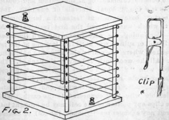
In constructing the tuning coil for sending, a great deal of latitude may be given in the choice of materials and their arrangement for use. One coil, which the writer has seen in use for some months, is of the bird-cage pattern, consisting of four upright strips mounted on a base board.
Following are the specifications as given by the builder: Four pieces of birch dowelling 3 ft. long and 1 in. in diameter; two pieces of whitewood or pine 10 in. square and 1 in. in diameter. In the corners of each square were bored 1 in. holes and the dowels fastened therein securely with glue. This forms a framework much like a hollow cage. Some very small screw eyes with holes just large enough to carry No. 12 bare copper wire were screwed into the corner posts on the outside, commencing at the bottom and continuing to the top at equal intervals of one inch. Into the bottom baseboard was fastened a large binding post to which was soldered the first terminal of the coil. Continuing, the wire passes through the screw eyes in coil or spiral form until the last one at the top is reached, where the end is also affixed to a binding post. All the woodwork is heavily shellacked. The flexible wire " d" which comes from one of the coil discharge knobs, has a metal spring clip, like the ordinary suspender clasp, on the free end, as does also the flexible wire "t" connected to the earth. With these clips any portion of the coil may be brought into use and any changes readily made, the coil, of course, being shut off while this is being done.
Continue to:


My Books

