


Tool Making For Amateurs. VIII. Inside Grinder Head for a Lathe
Description
This section is from the book "Amateur Work Magazine Vol4". Also available from Amazon: Amateur Work.
Tool Making For Amateurs. VIII. Inside Grinder Head for a Lathe
ROBERT GIBSON GRISWOLD
If you have ever tried to make an accurate fit in the case of a plug entering a hole, you have doubtless met with considerable difficulty. There are many methods used in machine work for making true, circular holes, but none approaching the inside grinder in results attained. A well sharpened reamer will do a beautiful piece of work when properly used, but after a reamer has once entered a hole and performed its work, it is very likely no longer to size, although the wear may be imperceptible. But continued use of this tool will soon place it in a position where it will be impossible to do a good job with it at all. And then, again, the reamer has its limitations. Unless the hole has a considerable depth, it is very difficult to make the reamer follow true ; it has a tendency to cut on one side or the other, depending upon how nearly vertical it is held, and if it is being driven by hand. This does not happen so frequently, however, when the reamer is used in a lathe and resting against the tail center.
But when it is necessary to make a ground fit, a fit that will allow of perfect freedom of movement and still allow no shake, then it is necessary to resort to a more accurate means of finishing the hole. This is the duty of the inside grinder, and it is indeed wonderful to see some of the classes of work that are done daily on this little tool. And then, again, the time saved is a very important factor, for by no other method can an equally good job be accomplished.
The inside grinder runs at a very high speed, far greater than that necessary for the outside grinder. This is due to the fact that the cutting speed of a wheel depends upon the velocity with which the surface of the work and the particles of emery pass each other. The higher the speed, naturally, the faster will the small particles cut into the comparatively soft steel or other metal. In the case of the outside grinder we have a wheel varying from two to three inches in diameter, while the wheel on the inside grinder is about 1/2 in. or less in diameter. The circumferences of any two circles are directly proportional to their respective diameters, and if we have an outside wheel that is 3 in. in diameter and running at 3,000 revolutions per minute its peripheral speed will be
3 x 3.1416 % 12 = 2356 feet per minute, while for the half-inch wheel to attain the same peripheral velocity will require a speed of 12 x 2356%.5 x 3.1416=18,000 revolutions per minute, or the revolutions vary inversely as the respective diameters of the wheels. It is seldom possible for the amateur to run his grinder at any such speed, and it is not necessary, as we will learn later.
Let us first look into the construction of the inside grinder. In Fig. 1 is shown a very simple but highly efficient inside grinder head complete with a micrometer adjustment. The base and micrometer arms are similar to those described in the last chapter. It may be well to state at this point why a combination tool grinder is not good for this class of work.
First and foremost, no tool carriage has a feed screw sufficiently fine to take cuts .0005 in., as the movement of the handle would be almost imperceptible to the touch. Then again, such a tool would at times be used for outside grinding and the bearing bushings would soon become worn (this is with reference to that type wherein the spindle may be worked to and fro with the hand) so that a clearance of .0004 in. or .0005 in. would exist, caused by fine particles of abrasive being carried in on the spindle and then grinding out the bushings. Now, when one attempted to use this on a very fine piece of work, either inside or out, he might be surprised to find out how much 2 x .0004 in. really means in close work.
It also requires more pressure to make an inside cutting wheel take hold of the work than an outside wheel. This is for the following reason: In Fig. 2 is shown the action between a piece of work and the outside wheel. The points of contact form a very narrow line, and it takes very little pressure to make the grains cut keenly. But now look at the case shown in Fig. 3. Here we have a half-inch wheel cutting inside of a one-inch hole. Notice how large the arc of contact now becomes. It takes considerably more pressure to make all these grains bite into the metal than in the case of Fig. 2.
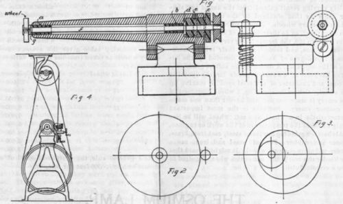
Now, if we were to place this little wheel on the end of a rapidly revolving spindle that overhung its bearing by say, three inches, and presented it to the work, we would find that the pressure that we were required to place on the spindle would bend it slightly, and as the wheel gradually took a deeper cut under the spring of the spindle, the hole would soon be ground with anything but a straight side or of a uniform diameter.
This leads us up to the design adopted in Fig. 1. Here the bearing is carried in an arm that extends close up to the wheel, thus taking all the bending strains, and, since it is necessary to have it only a little smaller than the diameter of the wheel, it can be made strong enough to be quite stiff against such strains. This arm carries a hardened steel bushing, a, at the end, and another at the center of the stock. These form the principal bearings for the spindle, which is made of tool steel, hardened and ground so that it runs with absolute truth. A soft steel or composition sleeve nut enters the stock at c, and bears against the shoulder d, preventing end play in the wheel. A small set screw, e, prevents the nut from backing out. This sleeve may be lined with a steel bushing, but the bearing is so long that it is hardly necessary, and the pull of the belt cannot be transmitted to the spindle and wheel, owing to the intermediate bearing, b. When the head is assembled, a quantity of thin oil is placed in the annular space, f, which keeps the bearing a and b well lubricated. It is an excellent scheme to keep a small felt washer, g, between the wheel and bearing a, to prevent the very fine particles of abrasive reaching the bearing.
As the spindle heats, as they always do under such high speed, the expansion is taken care of by the collar d, which allows the spindle to lengthen in either direction, but at the same time prevents end play. A very light belt is used to drive this grinder, and for this reason a twisted rawhide belt is far better than any other, owing to the grip that it takes on the pulley. Otherwise, the design is similar to that shown in the last chapter.
These grinders require an overhead drum or pulley, as shown in Fig. 4. This is simply a drum supported by two hangers and driven by a belt from the driving wheel of the lathe. The back gears of the lathe are thrown in, and the work is driven at a very slow speed, while the small wheels must be driven as fast as it is possible with foot power.
The drum may be made of a series of wood strips glued together to form the drum and afterwards turned in the lathe. As these strips are laid together the ends are nailed to the two flanges at the ends, and after all the strips are in place a cord is wrapped tightly around the whole, binding them all closely together until the glue is dry. It is then swung in the lathe and a small tool fitted to the tool post, having a very keen edge. A fine feed may then be used and the piece driven at a good rate of speed which will make a very nicely finished drum, especially after sandpaper has been applied. The drum need not be over six or seven inches in diameter.
The lead of the belting is shown in Fig. 4. If the drum is over three feet above the lathe, the increase and decrease of tension in the grinder belt will not matter much, but under that the strain will become greater as you feed away from the center. This can be accommodated by unhooking the two ends, untwisting slightly, and again joining together.
Now let us consider for a few minutes the question of the selection of the wheel. Perhaps in no other department of machine shop practice is there such a widely varying result gained from the use of two similar tools as that obtained by the use of different grades of emery wheels. Emery wheels are graded in two ways; first, as to their degree of fineness, running from No. 8 to 120, the former being very coarse and the latter very fine, and second, as to their relative hardness, This degree of hardness is denoted by the letters of the alphabet, A denoting the softest grade.
The hardness of a wheel depends largely upon the amount and character of material used in making up the wheel. Generally speaking, a wheel composed of fine emery is more compact and harder than one made of coarser emery. Softness is the most important characteristic in a wheel, as a soft wheel will be less likely to affect the temperature of the work or to glaze, and is best for grinding hardened steel, cast iron, brass, copper and rubber. For soft steel and iron, use a harder and more compact wheel. It might be said that the harder the work the softer the wheel required to give a certain finish.
The thickness of the wheel or width of the surface presented to the work also controls the degree of hardness to a certain extent. The narrower the wheel the harder should be the grade.
Below is given a table of the numbers representing the various grades of emery, and the degree of smoothness of surface they leave may be compared to that left by flat files as follows:
8 and 10 represents the cut of a wood rasp. 16 and 20 " " " " a coarse rough file.
24 and 30 " " " " " an ordinary rough file. 36 and 40 " " " " " a bastard file. 46 and 60 " " " " "a second-cut file. 70 and 80 " " " " " a smooth file. 90 and 100 " " " " " a superfine file. 120F and FF " " " " " a dead-smooth file.
The following table gives the average speeds for emery wheels as taken from the lists of various manufacturers :
Diam. of wheel | Rev. per min. |
1 in. | 15,000 |
1 1/2" | 12,500 |
2 " | 10,000 |
2 1/2" | 8,000 |
3 " | 7,000 |
4 " | 5,000 |
5 " | 4,000 |
6 " | 3,600 |
7 " | 3,000 |
As a general rule, the peripheral speed of a wheel should be about 5500 feet per minute.
Continue to:


My Books

