


A Gasoline Touring Car. III. Two Cylinder Air Cooled Engine
Description
This section is from the book "Amateur Work Magazine Vol4". Also available from Amazon: Amateur Work.
A Gasoline Touring Car. III. Two Cylinder Air Cooled Engine
R. G. GRISWOLD
As with every mechanism requiring a prime mover there exists a variety of motors that may be used for power purposes; in each class there also exists a number of types from which to select. The type adopted for this car has been chosen for several reasons, which will be enumerated.
As will be seen from Fig 7, it is a horizontal engine with two opposed cylinders. When well made this type of engine is in almost perfect balance, and runs at a high speed with remarkably little vibration, which can be scarcely felt in the car. The rating of any engine depends upon its revolutions, for one factor, while all others are supposed to remain constant. In this particular instance the rating is 15 h. p. at 1100 revolutions.
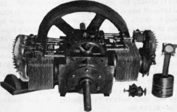
In regard to the cooling medium adopted, the illustration plainly shows that it is air. The air cooled motor, now being adopted by many of the largest automobile manufacturers, is free from many of the annoyances attending the water-cooled engine. There is no radiator, with its leaky tubes to bother with, no extra tank of water to carry, and no pump to drive. The saving in dead weight alone is a very important consideration.
The heat in this motor is carried away from the cylinder walls by means of copper flanges forced on. Copper has a high factor of conductivity for heat, and if sufficient area is given for the cooling action of the air, will keep the cylinder walls quite cool enough.
It is a popular fancy that a gasoline engine should be cooled down to a very low point, while the cylinders of a steam engine should be heated to as high a point as possible. But why so? They are both thermal engines, and certainly if the residual heat of the walls can be used to good advantage in the latter, why not in the former? The mathematical reasoning proves it to be a fact, so the fault must lie in some con-structual feature if trouble is experienced. The greatest fault is here: The sliding surfaces of the cylinders and pistons must be lubricated, and the high temperature readily chars the oil; but now that oil manufacturers have given us high-test oils, if we can keep the wall temperature down to about 500° we need have little trouble. Beyond the lubricant problem comes the valve stem question. The high temperatures of the exhaust gases will often cause the stems to warp, if sufficient shield is not provided, and this readily allows leakage past the valve.
In this type of engine the reciprocating parts can be mechanically balanced without the adoption of web balance weights. Owing to this fact the parts may be made very light without materially reducing their strength. The advantages of the four cycle type may be obtained and still have an impulse every revolution by placing the cranks 180° apart. With the vertical types this is only possible with the cranks together, and both pistons travelling in sychronism, and owing to a balance being effected by means of web weights attached to the cranks, the effect of the reciprocating parts can be balanced at one speed only.
Furthermore, this method entails considerably greater work in machining the parts. If vertical two-cycle cylinders are used. the cranks may be 180° apart and two impulses per revolution obtained, but this necessitates a two-part crank case with a middle bearing and its consequent inaccessibility, together with a far more deficiently machined shaft. All points considered, the horizontal opposed type is probably the best suited for amateur construction.
The cylinders are cooled by means of copper flanges forced on to the cylinder shell. This method is considered superior to that employing cast ribs, on account of lightness and the greater conductivity for heat of copper over cast iron. In this engine the valves are each carried in a separate casing, which may be readily removed for regrinding by inspection. The heaps and valves may be removed and replaced without disturbing any of the valve gear.
The completed engine is shown in Fig. 1 with one one piston and its rod standing beside the cylinder. The engine measures over cylinders, 26 1/4 in. and 12 7/8 in. in height, while the the crank shaft may be made anything over 15 in. The fly wheel is 19 in. in diameter with a 2 x3 in. run.
Fig. 2 shows the details of the crank case and cylinder. The bottoms of the feet should be planed first to give a solid foundation for setting while performing the other operations. Then face the seat for the crank shaft loose bearing. This gives a large surface to square by for facing and boring the cylinder seatings.
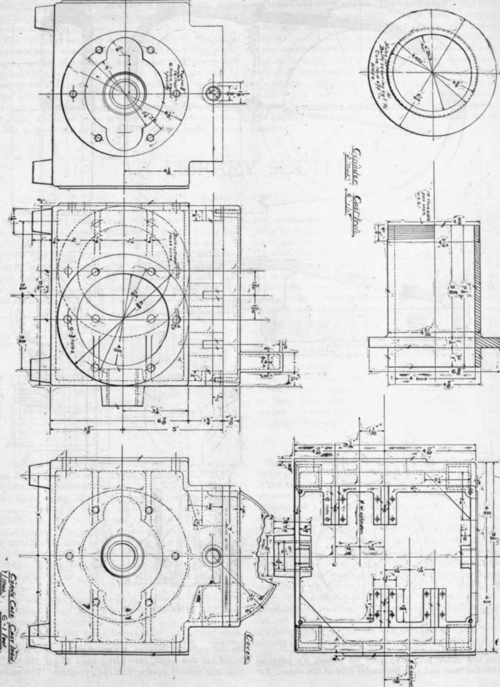
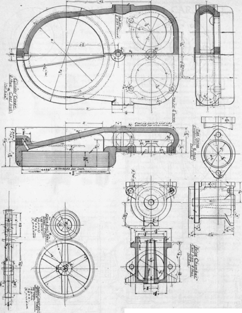
The top cover joint may now be planed up parallel with the feet, and also the under side of the cover. After the cylinder facings are finished the case may be bored for the shaft, care being used to get the shaft bearings exactly square with the cylinders. The loose bearings will be shown on another detail sheet. The bolt holes may now be located and drilled, which will practically finish the case.
The cylinders are very simple pieces and require no intricate lathe work. The outside is given a very slight taper, so that the copper flanges, as they are spread on, will be a very close, tight fit. Upon this close fit largely depends their good heat conducting qualities. The bolt holes in the cylinder should not be drilled until the heads have been fitted and the cylinders put in place, when the holes may be laid on from the case.
Fig. 3 shows the details of the cylinder heads, valve chambers and valve gears. The heads are divided into two compartments, one carrying the cool, incoming gases, and the other the exhaust gases. The spark plug is situated in the inlet chamber, where the cool, incoming gases sweep by it and clear all carbon or soot deposit from it. The cooling points and vanes have purposely been omitted from this drawing for the sake of clearness. The head screws up against an asbestos gasket which cannot blow out. The valve chambers are readily machined and need no further description. The various other details will be shown in the next chapter.
Continue to:


My Books

