


A Cheap Nine-Inch Reflector. V. Apparatus for Testing Lenses
Description
This section is from the book "Amateur Work Magazine Vol4". Also available from Amazon: Amateur Work.
A Cheap Nine-Inch Reflector. V. Apparatus for Testing Lenses
M. A. AINSLEY
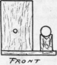
Presuming that the reader has mastered Chapter IV, giving the theory of the pinhole test at the center of curvature, I will briefly describe my apparatus: - It simply consists of a wooden baseboard (metal would be even better) to support the lamp, taken from a cheap bicycle, which gives a flame 1/2 in. wide. Immediately in front of the flame is a vertical wooden board (4 in.X 2 1/2 in.), which has a 1/2 in. hole level with the brightest part of flame. This supports, on the flame side, a brass plate with a hole 1.160 in. in diameter. This I got drilled by a watchmaker with a drill .15 millimetre in diameter. The plate with a hole in it can be easily removed or placed in position, and a screen of tin round the lamp shields the eye from its light.

Fig. 1,
Immediately to the left of this lamp, and so that its center line is not more than 2 1/2 in. from the pinhole, and on the same level, is a brass tube supported on two wooden Vs and, of course, parallel to the line joining flame, pinhole and mirror. A line is cut round the tube, accurately at right angles to its axis, as an index, and the position is measured by an ivory millimetre scale attached to the Vs; 1 mm. = 4-100 for all practical purposes, and it is easy to estimate to 1/4 mm., or 1-100 in. The mirror is supported against a stout board and rests on a shelf on the board. It is placed at a somewhat lower level than the apparatus. If the tube used is, as in my case, the "draw-tube" into which the e. p.'s screw, an efficient "occulting screen " be made by removing the lenses of a low-power eyepiece and using the diaphragm or stop, which limits the field of view.
The testing apparatus and speculum should be supported on firm supports, tripods if possible, on a stone floor; but testing may be carried on, as I found, even in an upper room, if it is done late at night so that no one is moving. The distance between pinhole and speculum is approximately twice the focal length; not exactly, because the image of the pinhole is a few inches further from the mirror than the pinhole itself. This makes no practical difference in testing, though if the pinhole were much nearer the mirror, the formula for aberration would have to be altered.
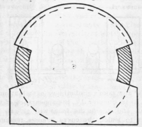
Fig. . 2
The screens used for hiding the parts of the mirror are two in number Figs. 1 and 2 and, these may with advantage be combined into one, Fig. 3. The central slide may be 2 to 2 1/2 in. in diameter, and the segment left in the outer zone, Fig. 2, may be 1 in. broad
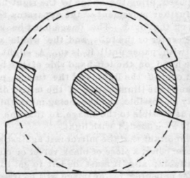
Fig. 3 and 3 in. long. I found the combined screen easiest to work with. Provide also a white paper cap to fit over the front end of the tube; this is useful in adjusting the position of the apparatus.
Light the lamp and see that the brightest part of the flame is opposite to the pinhole. Remove the pinhole and let the light shine on the mirror through the hole in the vertical board; place the tin screen round the lamp to darken the room; the room, of course must be otherwise dark, or nearly so. Then place the apparatus at a distance from the mirror, approximately equal to twice the focal length of the mirror, i. e. , the radius of the curvature. Move the mirror about until the image of the flams, seen through the 1/2 in. hole, is received on the paper cap at the end of tube; remove the paper cap and view the mirror through the tube, taking care that the tube is accurately pointed to the center of the mirror. Move the apparatus to or from the mirror until the image of the hole is at the eye end of the tube; insert the plate with the pinhole in the testing apparatus and focus the image with eyepiece or lens of some sort.

We may now take a preliminary examination of the image. As in Chapter IV, the appearance of the image inside and outside the focus will give an idea of the class to which the curve belongs, remembering that Class A (oblate spheriod) gives bright center outside and dark inside focus; Class B (sphere) gives the same uniform appearance inside and outside focus; Class C (ellipse, parabola, hyperbola) give bright center inside and dark center outside the focus.
Next, remove the lens, or lenses, and bring the image, by moving the apparatus to the edge of the screen used for testing, i. e., if the diaphragm of the eyepiece is being used, bring the image to the right-hand side, so that further movement of the apparatus to the left will cut off the light. The image must be kept level with the center of the tube, and the whole apparatus packed with paper until it is so. A slight pressure with the hand on the left-hand side of the baseboard will just cut off the light, and the tube is pushed or pulled until the illumination of the mirror disappears as evenly as possible, the eye being meanwhile placed as close as possible to the image, so that the mirror is seen as it were flooded with light.
It is important that the mirror rest against a backing of uniform color, a piece of black velvet or cloth being most suitable; also it must be left to get thoroughly cool after polishing, or the image will be irregular and the testing unsatisfactory.
The mirror must be handled as little as possible. A finger placed on the surface for a half a minute produces a slight elevation which is easily visible in testing; in fact, once the mirror is in position, it ought not to be touched at all until testing is completed.
Continue to:


My Books

