Turning A Crank-Shaft
Description
This section is from the book "Cassell's Cyclopaedia Of Mechanics", by Paul N. Hasluck. Also available from Amazon: Cassell's Cyclopaedia Of Mechanics.
Turning A Crank-Shaft
The adjoining sketches show one method of turning the crank-pin of a small crank-shaft of an engine, Fig. 1 being a front elevation and Fig. 2 a side view. Iron slabs, lettered A, are fastened, one at each turned end of the shaft B, by set screws C. The slab is centred at E, so that D in Figs. 1 and 2 represents the throw of the crank. Sometimes the hole in the slab is larger than the turned end of the shaft; the hole is then packed so that the distance 1) between the centres can he adjusted. To stiffen the system, long bolts at F are introduced, being jambed tight by nuts at the ends. The slabs are often to the shapes shown by the dotted lines in Fig. 2. The centres of the slabs and of the crank-pin must be in line, the positions being set by the aid of vee-blocks, plumb-bob, and scribing block.
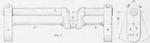
Turning a Crank-shaft for Engine.
Continue to:
My Books

