Strength Of Brick Arch
Description
This section is from the book "Cassell's Cyclopaedia Of Mechanics", by Paul N. Hasluck. Also available from Amazon: Cassell's Cyclopaedia Of Mechanics.
Strength Of Brick Arch
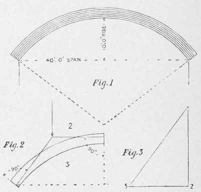
Here are hints on finding the strength of a brick arch by calculation, and also by construction. An example in which the span is 40 ft. and the rise 10 ft. is worked thus :- Span 40 ft. and rise 10 ft. will give, radius=(((1/2span)2/rise) +rise)/2 = ((202/10) +10)/2= 25ft.2.
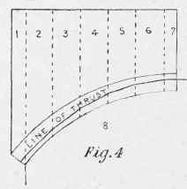
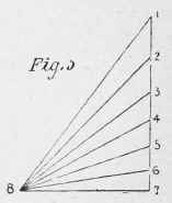
One rule for thickness of brick arch at crown = .4 √radius = '4 x √25 = 2 ft., in this case = 24/4 1/2=5 3/9say six half-brick rings. Another rule for railway viaducts is, number of half-brick rings = span in feet/(6 or7)=40/(6or7)=6 2/3to75/, say six half-brick rings. Then draw the arch, as in Fig. 1. From experience of the usual course of a line of thrust under a distributed load in a circular arch, it may be assumed that at the crown it will be at the joint between the fourth and fifth rings, while at the abutment it will be between the second and third rings, so thai its whole outline will occupy the middle third of the depth of arch ring. From these points draw lines at right angles to the thrust, and they will intersect at the spot where the half load may be considered to be applied. Before the reciprocal diagram of those forces can be drawn, and the amount of the load ascertained, the value of the horizontal thrust must be assumed; thus, suppose the maximum safe load to be 10 tons per square foot on brickwork, then the mean pressure over the whole depth of arch will be 5 tons per square foot, or with an arch 2ft. 3in. deep, a total pressure per foot run, through the arch, of 11.25 tons; this will be the measure for line 2 - 3in the stress diagram (Fig. 3); then drawing 3 - 1 parallel to the thrust at abutment in Fig. 2, and a vertical line for 2 - 1 to intercept it, the stress diagram is made complete, and from this the value of 1 - 2 is measured off. This will be the load on half of the arch, and double it will be the total distributed load on the arch, including weight of brickwork. It should then be checked by working the reverse way, starting with a distributed load, and finding the line of thrust and maximum pressure, as in Fig. 4 (stress diagram, Fig. 5), where the load on the arch is translated into cubic feet of brickwork placed above it, and the area of each 4-ft. width taken for weight on that part.
Strength of Brick Arch.
Continue to:
My Books

