Simple Metronomes
Description
This section is from the book "Cassell's Cyclopaedia Of Mechanics", by Paul N. Hasluck. Also available from Amazon: Cassell's Cyclopaedia Of Mechanics.
Simple Metronomes
A metronome, a device for measuring and beating time in music, may be made with a piece of tape and a weight, or it may be an elaborate clockwork arrangement. For the tape and weight metronome, the distances from the centre of the weight to the point of suspension should be as follow: -
A Simple Metronome.
No. of Beats per Minute. | Distance in Inches |
60 .......... | ..... 39.14 |
70 .......... | ...... 28.75 |
80 ......... | ...... 22.01 |
81 .......... | ...... 19.87 |
86 .......... | ..... 19.01 |
90 ......... | ...... 17.39 |
100 ......... | ...... 14.69 |
10.5 .......... | ...... 12.83 |
110 ......... | ...... 11.64 |
120 .......... | ...... 9.78 |
126 ......... | ...... 8.87 |
130 ........ | :.. 8-34 |
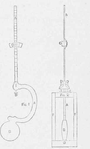
Slightly more advanced than the weighted tape in sus-pension is the metronome illustrated by Figs. 1 and 2. It is, however, of simple construction though it will answer quite as well as a more elaborate arrangement. Of the compound pendulum, A is the rod, B the bob, and C a small supplementary weight which slides up and down the upper part of the rod. With C at the top end the pendulum, on being set in motion, will swing for twenty minutes or more at the rate of about forty-eight beats to the minute; when C is at the bottom end, near the pivots, the pendulum will swing for a shorter time at the rate of about 141 to the minute. These matters having been determined by experiment, the intermediate speeds are measured off on the rod; the divisions are closer together as they approach the top, as shown at Fig. 1. The pendulum should be cast in brass, and only the top part of the rod, on which the weight is to slide, need be filed to 3/16 in. in breadth and ,',. in. in thickness. The pivots are shown at D (Figs. 1 and 2): they are two pins of tempered steel filed to a sharp point and driven tightly into holes drilled through the projections on the sides of the rod as shown in Fig. 2. The points work on a smooth piece of brass E (Fig. 2) which is slightly hollowed out on its top side in both directions for the purpose of enabling the pendulum to swing itself perpendicular when set up on an uneven surface. A small steel spring is screwed on one side of the weight C to keep the latter at any desired height, though it allows the weight to be slid easily up and down the rod when re mired. The bob B is placed slightly off the centre (to the left) to com pensate for the weight of the bend on the right. The stand has a mahogany base G (Fig. 2) 3 in. by 2 in. by 1/2 in., with two uprights F 51/2 in. by 3/4 in. by 1/4 in., and a cross-bar to support the brass plate E.
Continue to:
My Books

