


Principles Of Air-Gun Construction
Description
This section is from the book "Cassell's Cyclopaedia Of Mechanics", by Paul N. Hasluck. Also available from Amazon: Cassell's Cyclopaedia Of Mechanics.
Principles Of Air-Gun Construction
These are some hints on the mechanism and principles of construction of an air gun. Pigs. 1 and 2 explain the mechanism of two kinds of air-guns. In Fig. 1, A is a wrought-iron tube closed a tone end, and acting as a reservoir for compressed air; IS is the butt end of the front part of the barrel, screwing into L; Cis a thick metal plate with a central hole forming the seat ol the valve D; C is screwed or otherwise fixed in the bore of A, and closes it except for the valve seating; D is a cup-shaped valve, sometimes made of horn, fitting accurately in its seat in C. The fit is finally got by heating the plate C, etc., and allowing D to remain forced into its place by the air in A till all is cold. E is a spindle passing through the middle of D, of which it forms part, and sliding loosely through holes in V and G, which are two vertical metal rods, attached by each end to A and B respectively. A spiral spring keeps D pressed lightly against the seating in C. H and J are two plugs screwed into B from outside. J is bored right through, and H partly so, to receive K, which slides through J and into H. K is a round steel rod having two collars, L and M. L takes the pressure of a spring N, which forces K downwards, 31 preventing the latter from being forced out too far.
Til is a lever pivoted to K by a pin at P, working in a slot and turning on Q, another pin attached by either end to B. At B there is friction contact with one end of E. S is a conical valve in B, kept in its seat by T, a spring pressing it upwards. The barrel to the left of B is bored smooth, and a well-fitting plunger or piston at the end of a rod is pushed in at the muzzle. The air in the barrel is forced by the plunger against D, and enters A by passing between C and D. AVhen the piston is drawn out again, the valve S opens inwards, and lets air in to fill the vacuum. The bullet is then rammed into B. On pushing in K, the lever PR is turned on Q, and i: presses onE, thus forcing D back and allowing the air to escape from A and blow the bullet out. Fig. 2 shows another common form of air-gun, A being the stock of the gun, B the butt-end section of the barrel, and C the muzzle end.
The two sections into which the barrel is divided fit together accurately at D. The section B is fixed to the stock,whilst portion C turns on a pivot at E into the position shown by F. At G there is an ear to which the link H J is pivoted, and at the end J a plug or piston K is pivoted. This latter slides easily in LM.the air chamber. In O is fitted an air piston as indicated, kept in position by a piston-rod passing through a guide. Between the piston and guide is a strong steel spiral spring, which presses the piston towards the end L of the air chamber. In loading the gun the fore-part of the barrel is bent down into the position F, thus exposing the breech, and a dart can then he inserted. G comes to the positionGi, and the rod H J is forced into the posit ion N O. This forces K back to K1, and the piston hack w it ii it. The catch, pressed up by a spring, holds the piston in that position till the trigger is pulled. This draws down the catch and releases the piston, which is instantly forced back by the spiral spring. The rapid passage of the piston through the air chamber forces a blast through the air passage, and this blows out the dart. A spring bolt locks the barrel when the two parts are in line, but yields to the application of force when bending the barrel to load.
The arrows in Fig. 2 show the direction in which the several parts move. The illustrations can be regarded only as mere diagrams; they are not drawn proportionately, and only such parts as are necessary to make the description clear are shown.
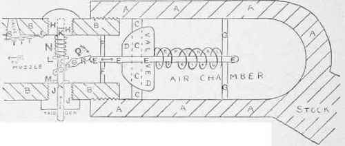

Principles of Air-gun Construction.
Continue to:


My Books

