Pattern For A Ship's Ventilator
Description
This section is from the book "Cassell's Cyclopaedia Of Mechanics", by Paul N. Hasluck. Also available from Amazon: Cassell's Cyclopaedia Of Mechanics.
Pattern For A Ship's Ventilator
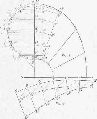
To cut the pattern for a ship's ventilator in four pieces, first draw a side elevation of the required size, then divide the throat curve into a number of equal parts, corresponding to the number of sections required for the ventilator. Next divide the top curve, forming the top of the ventilator into the same number of equal parts used for the throat, and also draw the semicircle A G (Fig. 1). Join the division points on the throat and top curve by straight lines; these would show the four sections whose patterns are to be developed. As the method of working would be the same for each section, the method adopted for the section A G, a2 gl (whose half-pattern is shown by Fig. 2), could be applied for developing the remaining three sections. A very near approximation to an accurate pattern is obtained by assuming that each section is a part of an oblique cone, and if this be done, the semicircle A <; (Fig. 1) would be the half-plan of the base of an oblique cone containing the first section. Now join Aa2 and G1 g1 and also draw a line from gl parallel to AG to cut Aa2; then this line could be assumed to show the smaller end of the frustum of the cone on the elevation. Draw projectors from al gl to join A G;, and with half this length as radius draw the semicircle a g to show the plan of the small end. Next divide the semicircles into a similar number of equal parts as a, B, C, a, b, c, etc. From the division points B, C, D, E., F draw projectors to A G1, and from b, c, d, e, f draw projectors to join a1gl. Join B1b1.C1e1. D1d1, E1e1, F1f1, and produce these lines to join a2g1 at b2, c2, d2,e2,f2. Join the division points on the plan by straight lines, and from b2, c2, d2, e2, f2 draw project ore to join the lines with corresponding letters on the plan, and if a curve were drawn through the points found, that curve would show the plan of the section of the ventilator on the line a2g1. Join the division points aB, Be, Cd, De, Ef.Fffby a series of dotted Lines, as shown, and these would be the plans of a series of diagonals joining the points indicated.
Next find the true Slants Of the stripes and diagonals by drawing lines at right angles to Bb.Cc, Dd, Ee, Ff.and on the lines drawn at right angles mark the upright height gg1, as shown. Join the division points on The inner circle to the points marking the upright height, and this would form a series of triangles; the slant length forming one side of the triangle would be the true slant of the line on the cone in each case. Next find the true slants of the dotted diagonals by the same method, using the same upright height as for the slants. The hypotenuse of the triangle formed in each case would be the true slant of the diagonal. To find the true slants of the lines above a1g1, where the projectors drawn from b2,c2, d2, e2, f2 join the lines with corresponding letters in plan; draw lines from the points found at right angles to the plan lines, and on these lines mark off the perpendicular height of b2, c2, d2, e2, f2 when measured from the line a1 gl. Now join b, c, d, e, f to their respective upright heights, marked on each right angle to obtain the true slants of the lines produced to cut a2 g1. To work the pattern, mark on a sti-aight line the length A1 a1 (Fig. 1). With the true length of the diagonal joining a to B as radius, and using a1 (Fig. 2) as centre, draw an arc; with the division length A B as radius and A1 (Fig. 2) as centre, cut the arc first drawn. Next, with the true slant of the line B b as radius, and using B' on the pattern as centre, draw an arc. With the division length a b as radius, and a1 on the pattern as centre, cut the arc last drawn at b1: this would give the points A1 a1, B1 b1 on the pattern. The remaining points are obtained by repeating the working for each division, using the slants and diagonals in their proper order for obtaining the points C1 c1, Dl dl, E1 e1, f1 F1 to complete the top part of the pattern. Join the points A1 a1, Bl b1, etc., on the pattern by straight lines, and produce them below the inner curve, then add the length a1 a2 (Fig. 1) from a1 to a2 on the pattern. Transfer the true slant of the line b1 b2 (obtained from the triangle drawn on the plan) to the pattern, marking from b1 to give the point b2; transfer the remaining true slants to the stripes with corresponding letters on the pattern, and draw a curve through these points to finish the half pattern for one section. By repeating the method of working shown for each section, the pattern lor the complete ventilator would be obtained. Allowances for hollowing, seams, etc., must be made to the pattern as shown.
Pattern for a Ship's Ventilator.
Continue to:
My Books

