Particulars Of Hydraulic Ram
Description
This section is from the book "Cassell's Cyclopaedia Of Mechanics", by Paul N. Hasluck. Also available from Amazon: Cassell's Cyclopaedia Of Mechanics.
Particulars Of Hydraulic Ram
The adjoining illustration gives a diagrammatic section of a hydraulic ram. A is an air vessel, B and C ball valves, D a delivery pipe, and E the supply pipe. Above the valve B is an opening, and the water, in running down from a small fall at E, passes through this outlet until the velocity is sufficient to close B. This, of course, suddenly stops the stream, and the outlet valve C is forced open owing to the great increase of pressure in the ram. Through C the water passes into A and up the delivery pipe D. This releases the pressure and the valves B and C fall and the operation is gone through again. In some cases an ordinary lift or a flap valve, which must be weighted to exceed slightly the static pressure of the supply stream, is placed between E and C. Obviously, a portion only of the supply water from a small fall is delivered to a greater height, and the average efficiency of the ram is probably not more than 50 per cent.
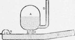
Section of Hydraulic Ram.
Continue to:
My Books

