Hydraulic Gradient And Sewage Irrigation
Description
This section is from the book "Cassell's Cyclopaedia Of Mechanics", by Paul N. Hasluck. Also available from Amazon: Cassell's Cyclopaedia Of Mechanics.
Hydraulic Gradient And Sewage Irrigation
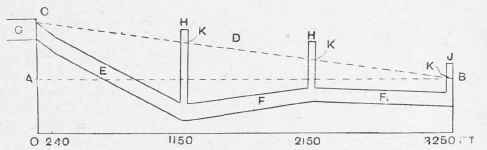
The hydraulic mean gradient of a sewer or water pipe is the line which would be assumed by the surface of an open stream when the discharge at the bottom was equal to that of the sewer or pipe,the cross section of thestream being assumed to be equal to the section of the pipe outlet. In the example shown in the figure, when the outlet at B is discharging at its fullest capacity, and there is an ample supply of sewage coming in at the other end of the sewer to maintain this discharge, the hydraulic mean gradient will be in the position shown by the dotted line B C. The vertical height between A and C is the head of water required to drive the sewage through the pipe at this particular rate, and measuring down from the hydraulic mean gi-adient to the pipe in any portion of its length, the vertical heights give the pressure tending to burst the pipe at that point. So long as this full discharge is maintained, the liquid will rise in the manholes to the height of the hydraulic mean gradient, and will consequently overflow at the weirs fixed at that height.
Supposing now that the supply of sewage were to diminish, and only a trickle come down the sewer, it is obvious that the sewer would gradually till up to the horizontal line A B, and then as soon as a trifling head of water had accumulated at the end A, the liquid would overflow at B. In this case the hydraulic mean gradient would be very nearly borizontal, and the sewage would not rise in the manholes sufficiently high to overflow at the weirs. For this reason the sluice valve is provided at the manhole at B. By shutting down this sluice to the required extent, the outlet can be made smaller, so that the water backs up in the sewer, and rises to the height of the weirs. The discharge will be very small compared with the discharge in the first case, but the hydraulic mean gradient will be in the same position. Reverting to the simile of the open channel on the line of the hydraulic mean gradient, it will be recognised that with a head equal to the distance between A and C there would be a large discharge if the channel were of a size equal to outlet of the pipe; but if the channel were of a cross section equal only in area to the diminished outlet when the sluice is partly closed, the same head of water will be required to drive a much smaller flow through the channel.
With respect to the sluice valve near the top end of the sewer, if its position is at 240 ft. on the horizontal line it can be brought into use, as it will be below the highest position of the hydraulic mean gradient. The letter references not already described are as follow. D, hydraulic mean gradient; E, pipes 30in. in diameter; F, pipes 24in. in diameter; G, open channel; H, manhole; J, manhole and sluice valve; and K, weir. It is obvious that the illustration is merely a diagram; it is not drawn to even approximate to any scale.
Hydraulic Gradient and Sewage Irrigation.
Continue to:
My Books

