How To Make A Cheap Drilling Machine
Description
This section is from the book "Cassell's Cyclopaedia Of Mechanics", by Paul N. Hasluck. Also available from Amazon: Cassell's Cyclopaedia Of Mechanics.
How To Make A Cheap Drilling Machine
Fig. 1 is an elevation of a drilling machine complete. The two wrought-iron uprights A should be l 1/4 in. wide, like the rest of the framework. Bend them first, care being taken to get the feet at right angles, and then cut them to length. Mark off the holes, two 7/16 in. in diameter for 3/6in. bolts for the cross-bars. In one upright an extra hole must be drilled | in. in diameter to take the hand-wheel shaft. This should be about midway between the 7/16in. holes, though the exact position depends on the diameter of the bevel wheels. Drill two 7/16 -in. holes in each foot for the holding-down bolts. The cross-bars B and C have 5/8-in. holes through the centre to take the spindle F. The key-way in the latter can be cut by a 3/16-in. cross-cut chisel, and afterwards cleaned out by a small square file. Next obtain a pair of bevel wheels of the same pitch, one wheel, if possible, having twice the teeth in the other. The wheels should be drilled 5/8 in., the key-way in the small wheel on the vertical spindle being parallel, that in the wheel for hand-wheel shaft E being slightly taper depthways. One end of the horizontal shaft must have a 3/16in. key-way, and the wheel should be knocked on and then keyed up by a small key, preferably with a head.
At the other end, the hand-wheel, from 8 in. to 10 in. in diameter, is attached either by a screw or by a square on the shaft. The wheel on the spindle F must work easily when a small parallel key is placed in the slot. The frame being bolted up, make the upright stay D so that it will just go between the two cross-bars; drill a 7/16in. hole at each end, and put the stay in position. Now with the spindle in position, with the wheel on as in Fig. 1, and with the other wheel in gear but off the shaft E, the 5/8-in. holes in D and A can be marked off, and also the holes in the cross-bars B and C. For the feed gear, a piece of brass or wrought iron may be cut to shape (Fig. 2), and two 7/16-in. holes and one 3/8-in. hole should be drilled through it, the |-in. hole being cut out afterwards. Round the spindle is coiled some brass wire, coils also being wound round the two studs which are fastened to the top cross-bar by 3/8-in. nuts. The two studs are screwed throughout the lengths. The feed is put on by a wing-nut on the centime stud, the springs Dringing the spindle back when the wing-nut is released. A coat of black enamel over the fixtures will greatly improve the appearance.
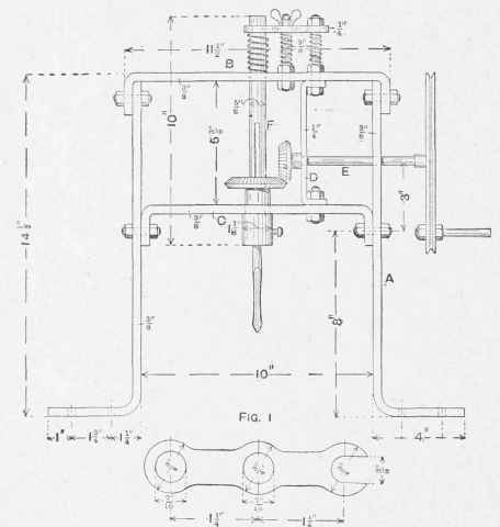
Fig. 2. How To Make a Cheap Drilling Machine.
Continue to:
My Books

