Construction Of Fireguard
Description
This section is from the book "Cassell's Cyclopaedia Of Mechanics", by Paul N. Hasluck. Also available from Amazon: Cassell's Cyclopaedia Of Mechanics.
Construction Of Fireguard
Fig. 1 shows the fireguard complete as it would stand round the fireplace. It should be of a size to fit against the centre of the mantelpiece jambs, and should stand about 30 in. high, though the height may be varied according to the position. The top rail should be of flat iron; in. wide by 1/4 in. thick, and the bottom bar 1 in. by 1/4 in. These are bent as shown in Fig. 1, leaving the ends 12 in. long. This size may be either less or more according to the size of the room. The rails are drilled to receive the standard bars at intervals, leaving 3in. space between the bars. The bars of round iron 3/8in. in diameter must be reduced at each end and then riveted into the rails (see section, Fig. 2). The back standard bar should be of flat iron 1 in. by Jin., with a round hole drilled through at 6 in. from the top to receive the screw on the plate, which is fixed to the mantelpiece, and to which the fireguard is secured by a thumb-nut (see Fig. 3). Another method of securing the guard to the mantelpiece is shown at Figs. 5 and 6. The top rail is turned down to form a hook, which falls into an iron eye on a plate fastened to the mantelpiece. The guard may be made more ornamental by using an angle-iron rail instead of flat iron for the bottom, and fixing on the front a brass ogee moulding (see Fig. 4) and on the top rail a half-round brass moulding (see Figs. 2 and 3). The guard may be painted dead black or any tint of enamel as individual taste may direct.
Fig. 1.
Fig. 2. Stephenson's Thermometer Screen.
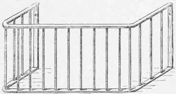
Fig. I.
Fig. 2.
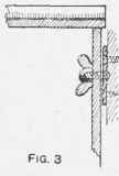
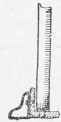
Fig. 4.
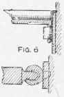
Fig. 6. Construction of Fireguard.
Continue to:
My Books

