Screw-Cutting Gear
Description
This section is from the book "The Mechanician, A Treatise On The Construction And Manipulation Of Tools", by Cameron Knight. Also available from Amazon: The mechanician: A treatise on the construction and manipulation of tools.
Screw-Cutting Gear
In connexion with the turning of piston-rods, crank-pins, and other objects, a few general instructions must be here given concerning screw-cutting wheels, including Tables of wheels for stated pitches, and methods of finding proper wheels when Tables are not available.
Tables Of Wheels
Before Tables of wheels can be understood, the wheels themselves must be considered, and the lathes to which they belong; therefore a few sketches are given in Plates 91 and 92, which indicate the ordinary arrangements of screwing-wheels for all lathes in general.
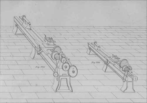
Plate 91
In Fig. 1125 an end of a lathe is shown having a set of screwing-wheels attached. The lathe-screw with which the slide-rest and its cutting-tool are moved along, need not be seen in this Figure, because it is presumed that the student has perused the general description of screwing-lathes in page 134. The wheels which impart the required motion to the lathe-screw are denoted by the four letters M, C, C, and S. The wheel M is fastened on the mandril or spindle of the lathe, and termed the mandril-wheel. This is the primary wheel of any set of wheels for screw-making, whether two, four, or any other number are employed; and it is by virtue of this wheel's motion being properly communicated to the lathe-screw by means of the wheel S, that all screws are cut. The proper arrangement of wheels for screw-cutting, therefore, consists in causing the primary wheel to so rotate the screw-wheel that it shall move exactly at the required rate to cut the desired screw.
There are two sorts of arrangements adopted for screw-cutting, which are termed simple gear and compound gear. An arrangement of simple-gear wheels consists of only two screwing-wheels, and a compound arrangement consists of four, or any greater number.
There are also two sorts of wheels used during screw-cutting - screwing-wheels and auxiliary wheels; these being termed, in page 176, connecting wheels. Connecting wheels are employed to occupy the space existing between a set of screwing-wheels, and to cause them to rotate in the direction required. Either one, two, or three of them may be used in conjunction with a set of screwing-wheels; but the connecting ones are never considered when referring to Tables, nor when calculating for wheels required, because each auxiliary rotates on its own spindle, independently of any of the screwing-wheel spindles. In the lig. (1125) the two connecting wheels are distinguished by C and C.
Screwing wheels themselves also consist of two classes, drivers and driven. These are conventional terms, because all the wheels are driven by the lathe-mandril; but it is convenient for reference, to name the primary or mandril-wheel of any simple gear arrangement a driver, and the screw-wheel of the same set a driven one. Also by analogy, to name the first and third of a compound set drivers, and the second and fourth driven.
The most usual wheels employed for screw-cutting, are those whose numbers of teeth advance by fives, from 15 to 150.
All the wheels which are used for a screw-cutting process, except the primary and the screw-wheel, are maintained in their proper places by means of a swivel-arm, in which two straight slots exist parallel with each other. This is termed a radiol, a portion of one being shown by R in Fig. 1125, and the whole of one, by R in Fig. 1126. The radiol is attached to a boss or flange belonging to the lathe-screw, and is capable of being raised or lowered while being swung on the screw-end as its pivot. Consequently all the screw-cutting wheels to be used may be caused to exactly engage with each other in their proper places. In the slot, or slots, one, two, or three, spindles are fastened; and after the wheels have been placed thereon, the spindles are slid along the slot, the radiol is adjusted, and all are fixed with a spanner.
The set of wheels in Fig. 1125 is a simple-gear arrangement for cutting a left-handed screw, supposing a right-handed lathe-screw is fitted to the lathe, the two connecting-wheels, C and C, serving to rotate the screw-wheel in the proper direction. To cut a right-hand screw, it is only needful to take off the two middle wheels, and put on a larger one of sufficient diameter to fill the space between the screwing-wheels. This will cause the screw-wheel to rotate in the opposite direction, but will not alter its rate of motion. It will therefore be perceived that the Tables of simple-gear wheels which are given, are applicable for cutting both right-handed screws and left-handed ones. These Tables are numbered 9 and 10. It is now necessary to mention the compound wheels.
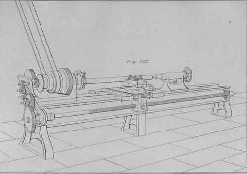
Compound wheels are represented in Fig. 1127. In this the four screwing-wheels are indicated by 1, 2, 3, and 4, the primary or mandril-wheel being shown by 1, and the next in order, which is a driven one, by 2. The third, shown by 3, is a driver, and rotates on the same spindle with No. 2. No. 4, is the screw-wheel, being a driven one and the last of the set. By employing these numbers, no confusion can arise from the variety of names which are given to these wheels by some persons; such as stud-wheel, axial wheel, intermediate wheel, pinion, spindle-wheel, and others. The two wheels shown by C and C, are connecting-wheels, and of any suitable diameters to communicate the motion from the mandril-wheel to the second one. By using C and C, the lathe-screw is caused to rotate in the same direction as the mandril and piece to be screwed; consequently a right-handed screw will be produced, because the lathe-screw is right-handed. It may be here mentioned that the lathe-screw will rotate in the same direction if the two auxiliary wheels are taken off, which is accordingly done when the screwing-wheels employed are large enough to engage with each other without auxiliary ones.
Continue to:
My Books

