Machine-shaping
Description
This section is from the book "The Mechanician, A Treatise On The Construction And Manipulation Of Tools", by Cameron Knight. Also available from Amazon: The mechanician: A treatise on the construction and manipulation of tools.
Machine-shaping
The various methods of shaping by paring-machines include cutting operations by means of drilling-machines, slotting-machines, and shaping-machines. It is therefore necessary to describe such machines, and to indicate their mode of action ; also to define whatever terms are ambiguous. Such terms will be frequently used in the details given concerning the shaping operations ; therefore considerable attention to names and to the action of the machines described is requisite.
Shaping-Machines
All paring-machines are shaping-machines; but that class which are specially named universal shaping-machines, are those which act with a short to-and-fro travel of their cutting tools, and are therefore distinct from what are termed planing-machines, because the cutting tool of a planing-machine is stationary during the time the metal in contact with the tool is being cut.
The class of ordinary shaping-machines which are at the present time in use are represented in Plates 64 and 65. In Plate 64, Fig. 829 represents what is termed a long-bed shaping-machine, and is capable of shaping objects which are comparatively long and slender. Fig. 831 also represents a long-bed machine, in which an object to be shaped is seen gripped with two vices belonging to the machine. Fig. 830 shows a short-bed machine, and is therefore only suitable for shaping small objects, or for shaping short portions of large objects.
Shaping-machines are actuated by means of leather bands, or india-rubber ones, which are connected with auxiliary shafts, such shafts being driven by other bands from the power-shaft of the factory. This means of imparting motive power to the shapers is denoted in Plate 64, and is similar to the mode of driving lathes. But shaping-machines are easily actuated in the same manner as planing-machines, by connecting the machine-bands with a shaft situated beneath the floor.
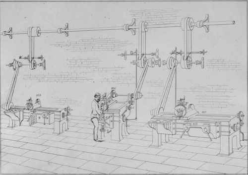
Plate 64
In Plate 65 the various portions in a machine of this class are indicated by letters and names, and such names belong to similar machines of all sizes, whether long or short, small or large. The fundamental portions of the machine consist of a long heavy portion termed the bed, and two pedestals or standards, on which the bed is bolted, unless it happens that the bed and standards constitute only one casting, which is the case in some small machines. On the top of the bed is situated the carriage, which slides along the entire length of the bed and fits any part of it by means of dove-tail surfaces. The upper portion of this carriage is provided with a dovetail gap, or with an angular gap of some class, for containing the slide portion or dove-tail of the moving head, in order that this part may easily move to and fro, and at the same time accurately fit the groove or gap in the carriage. Attached to the head, and often solid with it, is a circular flange-portion, named the flange, and shown by F, to which the slide-rest is connected. In front of the flange, a portion having a curved upper edge with worm-teeth is seen, termed the segment-rack or sector-rack, indicated by R, which portion is actuated by the worm-pinion and its spindle, denoted by W. Behind the worm-pinion is a straight slide, which is moved upwards and downwards by a screw within, which is not seen ; but the wheel shown at the top is the means of rotating the screw, and thereby moving the slide. The motion of this slide is the slide-rest's vertical traverse ; consequently the screw is termed the vertical traverse-screw. This slide, together with the other portions attached, are termed the slide-rest. The tool-holder is a portion connected to the sector-rack, and the two grippers or tool-clamps are denoted by T C. By means of the vertical traverse the tool which is fixed in the tool-holder is accurately adjusted to the precise height required, after an object to be shaped is fixed and is ready to be cut. This is the principal use of such a traverse, therefore the screw within the rest is only a few inches in length in the largest machines.
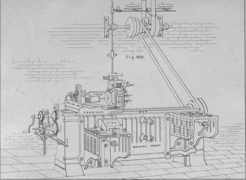
Plate 65
In order to properly place the article to be shaped, it is bolted to one or both of the chambered tables attached to the front of the machine. These tables can be fixed either close to each other or at any desired distance apart, to suit the intended shaping, being moved along the front grooves by rotating the screw. The exact height of a table when arranged for use depends on the thickness and shape of the piece which is on the table, the precise height being attained by working the screw in the chamber or space beneath.
The motion for moving the head to and fro, is obtained from the spindle belonging to the step-pulley at the back of the machine. To this spindle a small cog-wheel termed a pinion is keyed, the teeth of which are engaged with the teeth of a larger cog-wheel termed the power-wheel. The power-wheel is indicated by P W, and is connected with the crank-arm or lever-arm shown by L A, this being the arm which actuates the connecting-rod shown by C R, thereby moving the head slide-rest and tool to and fro in the manner desired. On the left-hand end of this spindle is connected a hollow cylindrical box, having the small gear for moving the cogwheels seen at the ends of both the horizontal traverse-screws, such motion being necessary while the machine is at work.
The operation of a machine of this class produces planes, by the tool-point being made to generate planes by its movement, while the article remains comparatively stationary on one or both tables; and the plane is generated by the traverse screw moving the carriage and tool-head along the bed at the same time that the tool is moved to and fro with the connecting-rod. For producing curved concave surfaces, the piece of work also remains stationary; but in such cases the carriage also is stationary, the tool-point being made to generate the curved figure desired by the to and fro motion of the tool combined with its curved motion, which curved motion is effected with the worm and sector-rack.
Some of these machines will also produce convex surfaces, such as the outer surfaces of lever-bosses. The movement required for such shaping is obtained by partly rotating the boss which is to be shaped. With this object a couple of conical pivots situated in front of the machine are made to tightly hold the lever-boss by placing it between each cone and screwing tight the fixing-bolt, a portion of each cone being in the boss-hole, this hole having been previously accurately bored. While thus held the pivots are made to rotate slowly, and consequently the lever also, the rotary movement resulting from the pivot-spindle having a worm-pinion and wheel attached to the long horizontal spindle within the machine. The circular motion of the boss being shaped, combined with the rectilineal motion of the tool-point in contact, produces the curved shape required for the outer surface of the boss, no rotation of the worm and sector being necessary. Shaping outsides of bosses, is however, more easily done with up-and-down slotters, which are next described.
The cutting tools that are required for shaping-machines, are of the same shapes as those for planing-machines, with the addition of a few tools which will be introduced in connexion with the details of processes.
Slotting-machines.
The slotting-machines here mentioned are those which work with an up-and-down vertical movement of their cutting tools, while the pieces being cut or slotted remain relatively stationary. It will be seen in future sections by the several sorts of shaping and slotting effected with shaping-machines, and slotting-machines, that both these classes of machines will perform the same class of slotting and shaping; so that a choice of two machines exists for shaping one object. The relative movements of both machines are about the same, but differ in direction; the tool of a shaper moving in a horizontal direction, and that of a slotter moving in a vertical direction. For engine-work in general it may be stated that a slotter is the more valuable machine of the two.
In their action all slotting-machines, small and large, resemble each other, and the entire class are represented by Fig. 834. By this Figure it will be seen that the machine mainly consists of a standard somewhat like a letter F, and a lower fundamental portion which supports a circular table in immediate connexion with sliding apparatus beneath. The F-shaped portion is that to which the whole of the apparatus for cutting is attached, and the lower portion is that to which all the slides, screws, and wheels for gradually moving and adjusting the work are connected. The cutting tool, by which the superfluous metal is cut from the object being slotted, is shown by its name, and its movement upwards and downwards is its only motion, excepting a small movement for releasing the tool's edge from the metal during the upward movement. The vertical motion of the tool results from its being attached to the main slide, and partaking of its motion. This slide is moved by the connecting-rod, C R, in the lower end of which is the crank-pin, which is attached to the wheel or disk rotated by the main shaft of the machine, to which shaft the step-pulley and its gear are connected. The machine-band of this gear is seen attached to the pulley, and also to the auxiliary shaft above.
The vertical motion of a slotting-tool combined with the comparative slow motion of the work and table beneath, together effect the slotting, or other shaping which may be in progress. The table, and consequently the object attached, is capable of three motions; and in this .capability consists the utility of the machine, the cutting tool being capable of only one motion. Beneath the circular table, and connected to it, are two sliding plates or slides, which move across each other in two directions, the one being at right angles to the other, the motion being similar to that of a slide-rest belonging to a planing-machine or to a shaper. The two motions are produced by the rotation of two screws within the apparatus, and, if necessary, both of these can be rotated at one time to produce a diagonal movement, across the machine. The third movement of the table is a rotary one; this is managed by providing a pivot at the centre of the table, by which means it is made to rotate, either singly or in conjunction with one of the rectilinear sliding motions To produce the rotary movement, the table is connected to a worm-wheel, shown by its name, in the teeth of which a worm-pinion is engaged, the pinion driving the wheel by being fastened to the spindle S. By reason of this spindle being connected with the rod and levers, which derive their motion from the pulley-spindle, the table is rotated, and also the object which is bolted to it, whenever such a movement is desired.
The small teeth-wheels shown near the table, are the means of rotating both of the traverse screw for the rectilineal motion, and also the worm pinion for the rotary motion, one of the wheels being on one end of the worm-spindle, and the others being on the ends of the two traverse-screws. These screws may be termed the slide-rest screws, because the entire sliding apparatus constitutes a large compound slide-rest.
Continue to:
My Books

