Benches
Description
This section is from the book "The Mechanician, A Treatise On The Construction And Manipulation Of Tools", by Cameron Knight. Also available from Amazon: The mechanician: A treatise on the construction and manipulation of tools.
Benches
Benches for drilling, screwing, tapping, lining, and filing are represented in Plate 31. In this Plate, Fig. 383 indicates a man who is lining a cylindrical piece of work in order to mark the centre at each end. For this purpose the work is put upon a pair of vee-blocks that rest on the lining table at which the operator is at work, and while the work is supported in the two vee-gaps, a scriber-block is placed upon the flat smooth surface of the lining table, and the point of the scriber is raised or lowered to about the centre of the work, and the workman then moves the block a short distance to mark a line upon the end ; after this he rotates the work with his left hand about a quarter of a complete rotation ; he then again moves the scriber and makes another short line; he next rotates the work another quarter of a rotation and makes another line; when he has thus made three short marks, he again moves the work to complete its rotation, and then marks a fourth line; these four lines enclose a small space, in the midst of which is the centre required. This centre is easily marked with a small dotting-punch, and is near enough to the exact centre for a great number of different sorts of work. After the operator has thus marked one end of the work, he puts the scriber-block to the other end and marks four other lines in a similar manner to indicate the other centre. If the piece of work thus marked is straight, the four lines made will indicate the centre of that extremity of the work which is near the scriber; but if not straight, the centre indicated merely denotes the axis of that portion of the work which touches the vee-gap during the process of scribing.
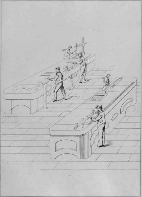
The lining table on which the scribing is being performed is of hard cast iron, or of Bessemer steel; it may be cast with a large recess at the under side, and in only one casting, or it may be made in two parts, consisting of the flat slab which is smoothly planed, and the lower framework which supports the slab. On the surface of the slab are marked several lines at right angles to each other, and two or three of them are divided into centimetres and millimetres, and also inches and parts, that the measures may be ready for the use of the workmen while lining or adjusting their work. Such a table seldom requires to be moved from its place, but if it is necessary to make it portable for use in various places, the making of the top slab distinct from the lower frame is advisable for heavy tables.
A bench for screwing, filing, and drilling is shown near the lining table. This bench may be made of either wood or plate iron riveted, and may be fixed or portable, so that it can be placed in the midst of an open space to allow several men to work, at all its four sides. At one of the vices, Fig. 385 represents a man filing a broad side of a straightedge, which is supported on a long block of wood about the length of the straight-edge. The wood is gripped in the vice at one end, and supported with a screw-prop at the other end ; and the straight-edge is fastened to the wood block with two screw-clamps; these clamps are moved to various places according to the part of the work being filed, so that the filing may be always performed on that portion of the work between the two clamps. Fig. 386 indicates a man working at a parallel vice; this is a vice which is without the usual straight leg reaching to the ground, the vice being entirely supported by the bench. A parallel vice forms a space between the two jaws, which is always parallel, whether a small space or a large one ; this is effected by making one of the jaws solid with the nut which contains the screw of the vice. By the jaw being thus solid with the nut, both move the same distance in the same time, and the desired parallel space is the result. Fig. 387 denotes a man scraping a piece of work which is edge upwards in the slit of a wood block supported on the lining table. Thin bars and straightedges may be thus held during a final scraping for the convenience of having the work near a plane surface, to which the work is applied to denote which part needs adjustment.
A convenient mode of drilling by hand is indicated by Fig. 391. The drilling apparatus consists of a strong pillar which is bolted to the bench, and on the pillar is an arm to sustain the pressure of the drill while in use; this arm may be swung around the pillar to any required place, and when a heavy piece of work is to be drilled, the arm may be placed over the work while it is on the floor, to avoid lifting it to the bench. In the arm of the drilling apparatus is a slot for attaching a hard steel plate having a few small conical recesses to hold the point of the screw in the drill-brace. This plate slides along the slot in the arm to the exact place required to suit the work to be drilled. An ordinary cranked brace is shown at work, but for large holes a ratchet-brace may be used having a long lever for exerting the necessary power.
Continue to:
My Books

