Chapter VIII. Wrought-Iron Columns
Description
This section is from the "Architectural Iron And Steel, And Its Application In The Construction Of Buildings" book, by WM. H. Birkmire.. Also see Amazon: Architectural Iron And Steel, And Its Application In The Construction Of Buildings.
Chapter VIII. Wrought-Iron Columns
119. Wrought-Iron Column Sections
What has been said in regard to "Rolled Iron Struts" in Chapter VI (Struts) applies also to wrought-iron columns.
The following compound sections of I beams, channels, angles, tees, and zee bars are frequently used.
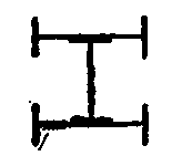
Fig. 1.

Fig. 2.
The section Fig. 1 of columns is composed of three I beams; the inner beam is riveted through its flanges to the webs of the outer beams by four lines of rivets.
In Fig. 2 channels are used on the outside in place of I beams; the flanges being turned inward gives the column a better finished appearance than Fig. 1.

Fig. 3.

Fig 4.
The section Fig. 3 is composed of two channels with latticing, or of two channels and plates riveted to the flanges of channels with four lines of rivets.
In Fig. 4 the section is composed of four corner angles with four plates, and joined together with eight lines of rivets.

Fig. 5.

Fig. 6.
The section Fig. 5 is formed in the same manner as Fig. 4, latticing being used in place of plates.
The rolled-segment or "Phoenix" column, as Fig. 6, is composed of from four to eight segments riveted together through the projecting flanges, and made from 4 to 17 1/8 inches outside diameter and 6 1/16 to 21 inches outside of flanges. Fillers of flat iron can be placed between these flanges to make up any required sectional area.
120. Zee-Bar Columns
Zee-Bar Columns represent types of columns with open sections, in common with I beam and channel columns, which readily admit of repainting and are therefore suitable for out-door work.
The standard sections of zee-bar columns, as shown on page 69, at Fig. 3, may be re-enforced to the required strength by using either three plates, as in Fig. 2, or making a square closed column, as in Fig. 1.
121. Strength Of Wrought-Iron Columns
Wrought-iron columns fail either by deflecting bodily out of a straight line, or by buckling of the metal between rivets or other points of support. Both actions may take place at the same time; but if buckling occurs alone, it may be an indication that the rivet spacing or the thickness of the metal is insufficient.
The rule has been deduced from actual experiments upon columns, as in girders, that the distance between centres of rivets should not exceed, in the line of strain, sixteen times the thickness of metal of the parts joined, and the distance between rivets or other points of support, at right angles to the line of strain, should not exceed thirty-two times the thickness.
122. Safe Load On Wrought-Iron Columns
On account of the perfect symmetry of form possessed by round and square sections, as compared with the shapes for which the table of "Safe Load on Struts" was especially calculated, the safe loads per square inch of section are increased ten (10) per cent for round columns and five (5) per cent for square columns. That is, the factors of safety previously given remaining the same, the ultimate strength is supposed to be 10 and 5 per cent, respectively, greater than the rolled struts.

The following tables give the values of the radius of gyration for round and square columns from 4 to 12 inches diameter and from 1/10 of an inch to 1 inch thick.
Note. - The weights given in the section of zee bars are pounds per foot in length.
123. Radii Of Gyration For Round Columns
Outside Diameter of Column in inches. | Thickness in inches, varying by Tenths. | |||||||||
.1 | .2 | .3 | 4 | .5 | .6 | .7 | .8 | .9 | 1.0 | |
Corresponding Radius of Gyration in inches. | ||||||||||
4 | 1.38 | 1.35 | 1.3I | I.28 | 1.25 | 1.22 | 1.19 | 1.16 | 1.14 | 1.12 |
5 | 1.73 | I.70 | 1.66 | 1.63 | 1.60 | 1.57 | 1.54 | 1.5I | 1.48 | 1.46 |
6 | 2.08 | 2.05 | 2.02 | 1.98 | 1.95 | 1 92 | 1.89 | 1.86 | 1.83 | 1.80 |
7 | 2.43 | 2.40 | 2.36 | 2.33 | 2.30 | 2.27 | 2.24 | 2.21 | 2.18 | 2.15 |
8 | 2.79 | 2.76 | 2.72 | 2.69 | 2.66 | 2.62 | 2.59 | 2.56 | 2.53 | 2.50 |
9 | 3.15 | 3.11 | 3 08 | 3.04 | 3.01 | 2.97 | 2 94 | 2.91 | 2.88 | 2.85 |
10 | 3.51 | 3.47 | 3.44 | 340 | 3.37 | 3.33 | 3.30 | 3.27 | 3.23 | 3.20 |
11 | 3.86 | 3.82 | 3.79 | 3.75 | 3.72 | 3.68 | 3.65 | 3.62 | 3.58 | 3.55 |
12 | 4.21 | 4.18 | 4.15 | 4.11 | 4.08 | 4.04 | 4.01 | 3.97 | 3.94 | 3.90 |
124. Radii Of Gyration For Square Columns
Outer Diameter across Flats in inches. | Thickness in inches, varying by Tenths. | |||||||||
.1 | .2 | .3 | 4 | .5 | .6 | .7 | .8 | •9 | 1.0 | |
Corresponding Radius of Gyration in inches. | ||||||||||
4 | 1.59 | 1.55 | 1.51 | 1.47 | 1.44 | 1.41 | 1.38 | 1.35 | I.32 | 1.29 |
5 | 2.00 | I.96 | 1.92 | 1.89 | 1.85 | 1.81 | 1.78 | 1.75 | 1.71 | 1.68 |
6 | 2.41 | 2.37 | 2.33 | 2.29 | 2.25 | 2.21 | 2.18 | 2.15 | 2.11 | 2.08 |
7 | 2.82 | 2.78 | 2.74 | 2.70 | 2.66 | 2.62 | 2.58 | 2.55 | 2.51 | 2.48 |
8 | 3.23 | 3.10 | 3.15 | 3.11 | 3.07 | 3.03 | 2.99 | 2.96 | 2.92 | 2.89 |
9 | 3.63 | 3.59 | 3.55 | 3.51 | 3.48 | 3.44 | 3.40 | 3.36 | 3.32 | 3.29 |
10 | 4.04 | 4.00 | 3.96 | 3.92 | 3.88 | 3.84 | 3.80 | 3.77 | 3.73 | 3.70 |
11 | 4.45 | 4.41 | 4.37 | 4.33 | 4.29 | 4.25 | 4.21 | 4.17 | 4.13 | 4.10 |
12 | 4.86 | 4.82 | 4.78 | 4.74 | 4.70 | 4.66 | 4.62 | 4.58 | 4.54 | 4.51 |
Example
What is the greatest safe load for a flat-ended round column 6 inches outer diameter, 1/2 inch thick, 8.64 square inches area, and 18 feet long?
r = 1.95, l/r = 111. By table of "Safe Load on Struts," Chapter VI (Struts), the corresponding safe load = 6780 + 10 per cent = 7460 lbs. per square inch of section, or 64,440 lbs. for the column.
For a square column add 5 per cent to the table instead of 10 per cent as above.
Continue to:
My Books

