5. Strainers. Plain Wrought-Iron Bar Window Guards. Bridle Or Stirrup Irons. Chimney Cap. Cast-Iron Flue Door And Frame. Wrought-Iron Flue Door. Flue Ring And Cover. Chimney Ladder. Corrugated Iron
Description
This section is from the "Architectural Iron And Steel, And Its Application In The Construction Of Buildings" book, by WM. H. Birkmire.. Also see Amazon: Architectural Iron And Steel, And Its Application In The Construction Of Buildings.
5. Strainers. Plain Wrought-Iron Bar Window Guards. Bridle Or Stirrup Irons. Chimney Cap. Cast-Iron Flue Door And Frame. Wrought-Iron Flue Door. Flue Ring And Cover. Chimney Ladder. Corrugated Iron
215. Strainers
Strainers are made of cast iron 3/8 of an inch thick, and perforated with 1/4-inch holes as shown. They are used principally in areas at the entrance of area drain pipe, to protect it from being clogged with refuse, and are made from 6 to 12 inches square.

216. Plain Wrought-Iron Bar Window Guards
Plain Wrought-Iron Bar Window Guards are made of 5/8 or 3/4 inch diameter bars, 4 or 5 inches apart between centres, secured to and extending through 1 1/2 X 3/8-inch or 1 1/2 X 1/2-inch cross-bars. These bars are let into the stone or brick reveals, as plan B, and halved on one side so the guards can be set after openings are built. They are also secured by screws to the window box, as shown at plan A. The vertical bars are further secured at the bottom by drilling holes into sill and leading in the bars.

217. Bridle Or Stirrup Irons
Bridle Or Stirrup Irons are used for wooden head-ers and trimmers to stairways, hoistways, floor lights, fireplaces and flues in all first-class buildings where the floors are supported by wooden beams.
In Fig. 1, W represents the width of iron, X the depth of header or supported beam, and Z the width of the same beam. The two views A show the twist as commonly used.

Section C is a double bridle for carrying opposite headers on one trimmer. Section B is the twist in opposite direction to that shown at A. The iron used for bridles is a medium grade cut to proper lengths; these are heated in a large furnace, bent and twisted in a machine, and completed in about fifteen seconds, in one heat, without hammering. They are of uniform strength and fitted to beams. The following sizes are commonly used:
Size of Beam. | Size of Iron. |
4"X 10" X 4"...... | 2" x 3/8" |
4"X 12" X4"..... | ..2" x3/8" |
4"X 14" X4"..... | ..2" x3/8" |
6" X 10" X 4" ..... | . • 2 1/2" x 3/8" |
6" X 10" X6"..... | . •2 1/2" X 3/8" |
6"X 12" X4"..... | • 2 1/2" X 3/8" |
Size of Beam. | Size of Iron. |
6" X 12" X 6"..... | . . 2 1/2" X 1/2" |
6"x 14" X 4"..... | .. 2 1/2" X 1/2" |
6" X 16" X6"..... | ..3" x 1/2" |
8" X 10" X 8"...... | ..3" x1/2" |
8" X 12" X 6"...... | ..3" x5/8" |
8" X 12" X 8"..... | ..3 1/2"x5/8" |
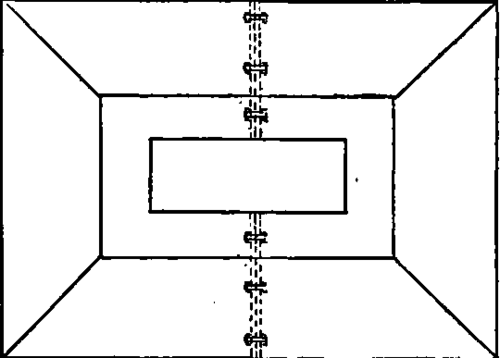

218. Chimney Cap
This cap is made of cast iron, 1/4 inch thick if small and 3/8 inch thick if the chimney is larger than 4 feet square. The outer lip of cap projects down, completely covering the upper layers of brickwork and protecting the mortar joints from the action of the weather.
The inside lip of the cap covers in the same manner the inside wall of air chamber, and extends down in flue from 8 to 12 inches.
The cap herein shown is made of two pieces; more will be needed if a top larger than 6 feet long is required.
219. Cast-Iron Flue Door And Frame
Cast-Iron Flue Door And Frame are used to en-close an entrance for cleaning boiler flues, and are built in with the brickwork. The frame is 3/8 of an inch thick, and cast with eyes for the pins of door hinge. The door is also 3/8 of an inch thick.

220. Wrought-Iron Flue Door
Wrought-Iron Flue Door is for a similar purpose as a cast-iron flue door, made of 1 1/4 X 3/8-inch flat iron covered with No. 16 gauge sheet iron, and hung to shutter eyes built in jamb. If no shutter eyes are used, the door frame is made of angle iron with hinges, and secured to the brick jamb.
221. Flue Ring And Cover
Flue Ring And Cover are used to enclose openings into flues when the stove pipe is not inserted. The size in general use is a 6-inch-diameter ring.
The ventilator is made similar in thickness, but square as shown in plate.

222. Chimney Ladder
Chimney Ladder is made of 3/4-inch-diameter bars bent the shape as shown, and placed in the wall of chimney when built. For easy climbing the rungs should be placed 12 inches apart between centres and about 18 inches wide, and project 6 inches from chimney. Where large chimneys are concerned they become useful at times, as the action of the weather often displaces the cap on chimney, and the ladder serves as a ready means of reaching the top.

223. Corrugated Iron
Corrugated Iron is used for roofs, sides of bulkheads, sides of buildings and sheds; also for arches in floors of buildings.
For roofs it is usually laid directly upon the purlins, and held in position by clips of hoop iron, which encircle the purlins and are placed about 12 inches apart.
For bulkheads, etc., the angle and tee iron uprights have 5/16-inch-diameter holes drilled about 12 inches apart between centres; the corrugation is then overlapped and riveted with 1/4-inch-diameter rivets through these holes.

As shown in Fig. A, B is the depth of corrugation, and A is the width, which varies from 2 to 5 inches. Fig. B illustrates the manner of application as arches between I beams.
In securing the corrugated iron to purlins on roofs, the bolts, screws and rivets must be in the ridges and not in the valleys of the corrugation.
Continue to:
My Books

