External Shear And Bending Moment. Part 4
Description
This section is from the book "Cyclopedia Of Architecture, Carpentry, And Building", by James C. et al. Also available from Amazon: Cyclopedia Of Architecture, Carpentry And Building.
External Shear And Bending Moment. Part 4
3. Compute the values of the bending moment in example 1, taking into account the weight of the beam, 400 pounds. (The right and left reactions are respectively 3,900 and 2,500 pounds; see example 3, Art. 33.)
We proceed as in example 1, except that the moment of the weight of the beam to the left of each section (or to the right when computing from forces to the right) must be included in the respective moment equations. Thus, computing from the left,
M0 | = | 0 | |||||||||
M1 | = | + | 2,500 | X | 1 | - | 40x½ | = | + | 2,480 foot-pounds, | |
M2 | = | + | 2,500 | X | 2 | - | 1,000 | X | 1 | - | 80X1=+ 3,920, |
M3 | = | + | 2,500 | X | 3 | - | 1,000 | X | 9 | - | 120X1½ = + 5,320, |
M4 | = | + | 2,500 | X | 4 | - | 1,000 | X | 3 | - | 160X2=+6,680, |
M.5 | = | + | 2,500 | X | 5 | - | 1,000 | X | 4 | - | 200'X2½ =+8,000, |
M6 | = | + | 2,500 | X | 6 | - | 1,000 | X | 5 | - | 240X3= + 9,280. |
Computing from the right,
M7 | = | - | (-3,900 | X | 3 | + | 3,000 | x | 1 | + | 120 | X | 1½) | = | + | 8,500, | ||
M8 | = | - | (-3,900 | X | 2 | + | 80 | X | 1) | = | + | 7,720, | ||||||
M9 | = | - | (-3,900 | X | 1 | + | 40 | X | ½) | = | + | 3,880, | ||||||
M10 | = | 0. | ||||||||||||||||
Examples For Practice
1. Compute the values of the bending moment for sections one foot apart, beginning one foot from the left end of the beam represented in Fig. 10, neglecting the weight of the beam. (The right and left reactions are 3,300 and 4,000 pounds respectively; see example 2, Art. 33.)
Ans. (in foot- pounds) | M1 | = | - | 2,100 | M6. | = | + | 3,400 | Mn | = | + | 2,100 | M16 | = | _ | 6,400 |
M2 | = | - | 4,200 | M7. | = | + | 5,300 | Mu= | = | + | 400 | M17 | = | - | 4,800 | |
M3 | = | - | 2,300 | M8 | = | + | 7,200 | M13 | = | - | 1,300 | M18 | = | - | 3,200 | |
M4 | = | - | 400 | M9 | = | + | 5,500 | M14 | = | - | 3,000 | M19 | = | - | 1,600 | |
M5. | = | + | 1,500 | M10 | = | + | 3,800 | M15 | = | - | 4,700 | M20 | = | 0 |
2. Solve the preceding example, taking into account the weight of the beam, 42 pounds per foot. (The right and left reactions are 3,780 and 4,360 pounds respectively; see example 4, Art. 33.)
Ans. (in foot- pounds) | M1 | = | - | 2, 121 | M6 | = | + | 4,084 | M11 | = | + | 2,799 | MI6- | = | - | 6,736 |
M2 | = | - | 4,284 | M7 | = | + | 6,071 | M12 | = | + | 976 | M17 | = | - | 4,989 | |
M3 | = | - | 2,129 | M8 | = | + | 8,016 | M13 | = | - | 889 | M18 | = | - | 3,284 | |
M4 | = | - | 16 | M9 | = | + | 6,319 | M14 | = | - | 2,796 | M19 | = | - | 1,621 | |
M5 | = | + | 2,055 | M10 | = | + | 4,580 | M15 | = | - | 4,745 | M20 | = | 0 |
3. Compute the bending moments for sections one foot apart, of the beam represented in Fig. 11, neglecting the weight. (The right and left reactions are 1,444 and 1,556 pounds respect-ively; see example 1, Art. 33.)
Ans. (in foot- pounds) | M1 | = | + | 1,556 | M5 | = | + | 5,980 | M9 | = | + | 6,104 | M13 | = | + | 4,328 |
M2 | = | + | 3,112 | M6 | = | + | 6,936 | M10 | = | + | 5,660 | M14 | = | + | 2,884 | |
M3 | = | + | 4,068 | M7 | = | + | 6,992 | M11 | = | + | 5,216 | M15 | = | + | 1,440 | |
M4 | = | + | 5,024 | M8 | = | + | 6,548 | M12 | = | + | 4,772 | M16 | = | 0 |
4 Compute the bending moments at sections one foot apart in the beam of Fig. 12, taking into account the weight of the beam, 800 pounds, and a uniform load of 500 pounds per foot. (The right and left reactions are 4,870 and 11,930 pounds respectively; see Exs. 3 and 4, Art. 33.)
Ans. (in foot- pounds) | M1 | = | - | 270 | M6 | = | - | 19,720 | M„ | = | + | 3,980 | M16 | = | 12,180 |
M2 | = | - | 3,080 | M7 | = | - | 13,300 | M12 | = | + | 6,700 | M17 | = | 12,200 | |
M3 | = | - | 6,430 | M8 | = | - | 7,420 | MI3 | = | + | 8,880 | M18 | = | 8,680 | |
M4 | = | - | 10,320 | M9 | = | - | 3,080 | M14 | = | + | 10,520 | M19 | = | 4,620 | |
M5 | = | - | 14,750 | M10 | = | + | 720 | M15 | = | + | 11,620 | M20 | = | 0 |
44. Moment Diagrams. The way in which the bending moment varies from section to section in a loaded beam can be well represented by means of a diagram called a moment diagram. To construct such a diagram for any loaded beam,
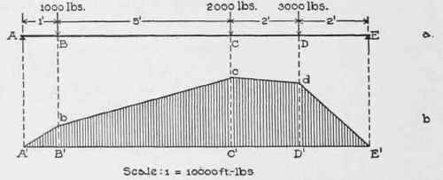
Fig. 17.
1. Lay off a base-line just as for a shear diagram (see Art. 38).
2. Draw a line such that the distance from any point of it to the base-line equals (by some scale) the value of the bending moment at the corresponding section of the beam, and so that the line is above the base where the bending moment is positive and below it where it is negative. (This line is called a "moment line.")
Examples. 1. It is required to construct a moment diagram for the beam of Fig. 17, a (a copy of Fig. 9), loaded as there shown.
Layoff A'E' (Fig. 17, b) as a base. In example 1, Art. 43, we computed the values of the bending moment for sections one foot apart, so we erect ordinates at points of A'E' one foot apart, to represent the bending moments.
We shall use a scale of 10,000 foot-pounds to the inch; then the ordinates (see example 1, Art. 43, for values of M) will be:
One foot from left end, | 2,300 | ÷ | 10,000 | = | 0.23 | inch, | ||||
Two feet | " | " | " | 3,600 | ÷ | 10,000 | = | 0.36 | " | |
Three | " | " | " | " | 4,900 | ÷ | 10,000 | = | 0.49 | " |
Four | " | " | " | " | 6,200 | ÷ | 10,000 | = | 0.62 | " |
etc., | etc. | |||||||||
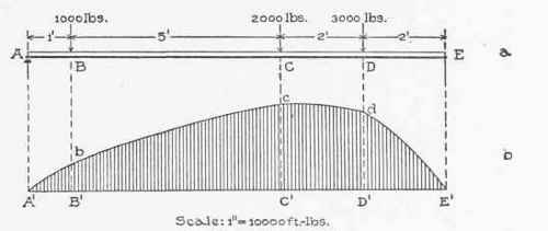
Fig. 18.
Laying these ordinates off, and joining their ends in succession, we get the line A'bcdE', which is the bending moment line. Fig. 17, b, is the moment diagram.
2. It is required to construct the moment diagram for the beam, Fig. 18, a (a copy of Fig. 9), taking into account the weight of the beam, 400 pounds.
The values of the bending moment for sections one foot apart were computed in example 3, Art. 43. So we have only to lay off ordinates equal to those values, one foot apart, on the base A'E' (Fig. 18, b).
To a scale of 10,000 foot-pounds to the inch the ordinates (see example 3, Art. 43, for values of M) are:
At left end, 0 | ||||||||||
One foot from left end. | 2,480 | ÷ | 10,000 | = | 0.248 | inch | ||||
Two feet | " | " | " | 3,920 | ÷ | 10,000: | = | 0.392 | " | |
Three | " | " | " | " | 5,320 | ÷ | 10,000 | = | 0.532 | " |
Four | " | " | " | " | 6,680 | ÷ | 10,000 | = | 0.668 | " |
Laying these ordinates off at the proper points, we get A'bcdE as the moment line.
3. It is required to construct the moment diagram for the cantilever beam represented in Fig. 19, a, neglecting the weight of the beam. The bending moment at B equals
- 500 x 2=-l,000 foot-pounds; at C,
-500 X 5-1,000 X 3=-5,500; and at D,
-500 X 9-1,000 X 7-2,000 X 4= -19,500.
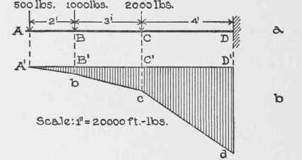
Fig. 19.
Using a scale of 20,000 foot-pounds to one inch, the ordinates in the bending moment diagram are:
AtB, 1,000-=-20,000=0.05 inch,
" C, 5,500÷20,0C0=0.275 "
" D, 19,500 ÷ 20,000=0.975 " Hence we lay these ordinates off, and downward because the bending moments are negative, thus fixing the points b, c and d. The bending moment at A is zero; hence the moment line connects A b, c and d. Further, the portions Ab, bc and cd are straight, as can be shown by computing values of the bending moment for sections in AB, BC and CD, and laying off the corresponding ordinates in the moment diagram.
4. Suppose that the cantilever of the preceding illustration sustains also a uniform load of 100 pounds per foot (see Fig. 20, a). Construct a moment diagram.
First, we compute the values of the bending moment at several sections; thus,
M1 | = | - | 500 | X | 1 | - | 100 | X | ½ | = | - | 550 | foot-pounda, | ||||||||||||
M2 | = | - | 500 | X | 2 | - | 200 | X | 1 | = | - | 1,200, | |||||||||||||
M3 | = | - | 500 | X | 3 | - | 1,000 | X | 1 | - | 300: | X | 1½ | = | - | 2,950, | |||||||||
M4 | = | - | 500 | X | 4 | - | 1,000 | X | 2 | - | 400: | X | 2 | = | - | 4,800, | |||||||||
M5 | = | - | 500 | X | 5 | - | 1,000 | X | 3 | - | 500 | X | 2½ | = | - | 6,750, | |||||||||
M6 | = | - | 500 | X | 6 | - | 1,000 | X | 4 | - | 2,000 | X | 1 | - | 600 | X | 3 | = | - | 10,800, | |||||
M7 | = | - | 500 | X | 7 | - | 1,000 | X | 5 | - | 2,000 | X | 2 | - | 700 | X | 3½ | = | - | 14,950, | |||||
M8 | = | - | 500 | X | 8 | - | 1,000 | X | 6 | - | 2,000 | X | 3 | 800 | X | 4 | = | - | 19,200, | ||||||
M9 | = | - | 500 | X | 9 | - | 1,000 | X | 7 | - | 2,000 | X | 4 | - | 900 | X | 4½ | = | - | 23,550. | |||||
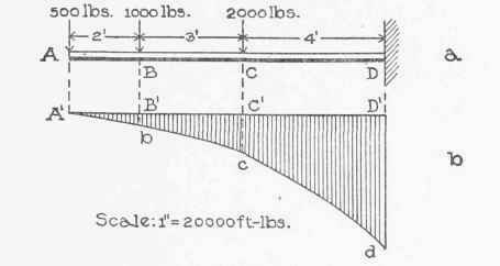
Fig. 20.
These values all being negative, the ordinates are all laid off downwards. To a scale of 20,000 foot-pounds to one inch, they fix the moment line A'bcd.
Examples For Practice
1. Construct a moment diagram for the beam represented in Fig. 10, neglecting the weight of the beam. (See example I, Art. 43).
2. Construct a moment diagram for the beam represented in Fig. 11, neglecting the weight of the beam. (See example 3, Art. 43).
3. Construct the moment diagram for the beam of Fig. 12 when it sustains, in addition to the loads represented and its own weight (800 pounds), a uniform load of 500 pounds per foot. (See example 4, Art. 43.)
4. Figs, a, cases 1 and 2, page 55, represent two cantilever beams, the first bearing a load P at the free end, and the second a uniform load W. Figs, c are the corresponding moment diagrams. Take P and W equal to 1,000 pounds, and I equal to 10 feet, and satisfy yourself that the diagrams are correct.
Continue to:
My Books

