Transverse Or Bending Strength: Beams
Description
This section is from the book "The Mechanical Properties Of Wood", by Samuel J. Record. Also available from Amazon: The Mechanical Properties Of Wood.
Transverse Or Bending Strength: Beams
When external forces acting in the same plane are applied at right angles to the axis of a bar so as to cause it to bend, they occasion a shortening of the longitudinal fibres on the concave side and an elongation of those on the convex side. Within the elastic limit the relative stretching and contraction of the fibres is directly9] proportional to their distances from a plane intermediate between them - the neutral plane. (NP in Fig. 15.) Thus the fibres half-way between the neutral plane and the outer surface experience only half as much shortening or elongation as the outermost or extreme fibres. Similarly for other distances. The elements along the neutral plane experience no tension or compression in an axial direction. The line of intersection of this plane and the plane of section is known as the neutral axis (N A in Fig. 15.) of the section.
[Footnote 9: While in reality this relationship does not exactly hold, the formulæ for beams are based on its assumption.]
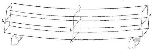
Figure 15
Diagram of a simple beam. NP = neutral plane, N A = neutral axis of section R S.
If the bar is symmetrical and homogeneous the neutral plane is located half-way between the upper and lower surfaces, so long as the deflection does not exceed the elastic limit of the material. Owing to the fact that the tensile strength of wood is from two to nearly four times the compressive strength, it follows that at rupture the neutral plane is much nearer the convex than the concave side of the bar or beam, since the sum of all the compressive stresses on the concave portion must always equal the sum of the tensile stresses on the convex portion. The neutral plane begins to change from its central position as soon as the elastic limit has been passed. Its location at any time is very uncertain.
The external forces acting to bend the bar also tend to rupture it at right angles to the neutral plane by causing one transverse section to slip past another. This stress at any point is equal to the resultant perpendicular to the axis of the forces acting at this point, and is termed the transverse shear (or in the case of beams, vertical shear).
In addition to this there is a shearing stress, tending to move the fibres past one another in an axial direction, which is called longitudinal shear (or in the case of beams, horizontal shear). This stress must be taken into consideration in the design of timber structures. It is maximum at the neutral plane and decreases to zero at the outer elements of the section. The shorter the span of a beam in proportion to its height, the greater is the liability of failure in horizontal shear before the ultimate strength of the beam is reached.
Continue to:
My Books

